This document provides information on various bulk deformation processes used to shape metals, including forging, rolling, extrusion, drawing, and swaging. It discusses the general characteristics, applications, advantages/disadvantages, and costs associated with each process. Diagrams are also included to illustrate stages of specific processes like impression die forging, thread rolling, and shape rolling. The document contains a comprehensive overview of common bulk deformation techniques for metalworking.
This chapter aims to provide basic backgrounds of different types of machining processes and highlights on an understanding of important parameters which affects machining of metals with their chip removals.
Metal cutting or Machining is the process of producing workpiece by removing unwanted material from a block of metal. in the form of chips. This process is most important since almost all the products get their final shape and size by metal removal. either directly or indirectly.
The major drawback of the process is loss of material in the form of chips. In this chapter. we shall have a fundamental understanding of the basic metal process.
Fundamentals of Metal cutting and Machining Processes
MACHINING OPERATIONS AND MACHINING TOOLS
Turning and Related Operations
Drilling and Related Operations
Milling
Machining Centers and Turning Centers
Other Machining Operations
High Speed Machining
Basic concepts of forging process are included.Forging is a very important production process as we know.To learn about forging,this slides would help you a lot.
Saudi Arabia stands as a titan in the global energy landscape, renowned for its abundant oil and gas resources. It's the largest exporter of petroleum and holds some of the world's most significant reserves. Let's delve into the top 10 oil and gas projects shaping Saudi Arabia's energy future in 2024.
Event Management System Vb Net Project Report.pdfKamal Acharya
In present era, the scopes of information technology growing with a very fast .We do not see any are untouched from this industry. The scope of information technology has become wider includes: Business and industry. Household Business, Communication, Education, Entertainment, Science, Medicine, Engineering, Distance Learning, Weather Forecasting. Carrier Searching and so on.
My project named “Event Management System” is software that store and maintained all events coordinated in college. It also helpful to print related reports. My project will help to record the events coordinated by faculties with their Name, Event subject, date & details in an efficient & effective ways.
In my system we have to make a system by which a user can record all events coordinated by a particular faculty. In our proposed system some more featured are added which differs it from the existing system such as security.
COLLEGE BUS MANAGEMENT SYSTEM PROJECT REPORT.pdfKamal Acharya
The College Bus Management system is completely developed by Visual Basic .NET Version. The application is connect with most secured database language MS SQL Server. The application is develop by using best combination of front-end and back-end languages. The application is totally design like flat user interface. This flat user interface is more attractive user interface in 2017. The application is gives more important to the system functionality. The application is to manage the student’s details, driver’s details, bus details, bus route details, bus fees details and more. The application has only one unit for admin. The admin can manage the entire application. The admin can login into the application by using username and password of the admin. The application is develop for big and small colleges. It is more user friendly for non-computer person. Even they can easily learn how to manage the application within hours. The application is more secure by the admin. The system will give an effective output for the VB.Net and SQL Server given as input to the system. The compiled java program given as input to the system, after scanning the program will generate different reports. The application generates the report for users. The admin can view and download the report of the data. The application deliver the excel format reports. Because, excel formatted reports is very easy to understand the income and expense of the college bus. This application is mainly develop for windows operating system users. In 2017, 73% of people enterprises are using windows operating system. So the application will easily install for all the windows operating system users. The application-developed size is very low. The application consumes very low space in disk. Therefore, the user can allocate very minimum local disk space for this application.
Cosmetic shop management system project report.pdfKamal Acharya
Buying new cosmetic products is difficult. It can even be scary for those who have sensitive skin and are prone to skin trouble. The information needed to alleviate this problem is on the back of each product, but it's thought to interpret those ingredient lists unless you have a background in chemistry.
Instead of buying and hoping for the best, we can use data science to help us predict which products may be good fits for us. It includes various function programs to do the above mentioned tasks.
Data file handling has been effectively used in the program.
The automated cosmetic shop management system should deal with the automation of general workflow and administration process of the shop. The main processes of the system focus on customer's request where the system is able to search the most appropriate products and deliver it to the customers. It should help the employees to quickly identify the list of cosmetic product that have reached the minimum quantity and also keep a track of expired date for each cosmetic product. It should help the employees to find the rack number in which the product is placed.It is also Faster and more efficient way.
CFD Simulation of By-pass Flow in a HRSG module by R&R Consult.pptxR&R Consult
CFD analysis is incredibly effective at solving mysteries and improving the performance of complex systems!
Here's a great example: At a large natural gas-fired power plant, where they use waste heat to generate steam and energy, they were puzzled that their boiler wasn't producing as much steam as expected.
R&R and Tetra Engineering Group Inc. were asked to solve the issue with reduced steam production.
An inspection had shown that a significant amount of hot flue gas was bypassing the boiler tubes, where the heat was supposed to be transferred.
R&R Consult conducted a CFD analysis, which revealed that 6.3% of the flue gas was bypassing the boiler tubes without transferring heat. The analysis also showed that the flue gas was instead being directed along the sides of the boiler and between the modules that were supposed to capture the heat. This was the cause of the reduced performance.
Based on our results, Tetra Engineering installed covering plates to reduce the bypass flow. This improved the boiler's performance and increased electricity production.
It is always satisfying when we can help solve complex challenges like this. Do your systems also need a check-up or optimization? Give us a call!
Work done in cooperation with James Malloy and David Moelling from Tetra Engineering.
More examples of our work https://www.r-r-consult.dk/en/cases-en/
Immunizing Image Classifiers Against Localized Adversary Attacksgerogepatton
This paper addresses the vulnerability of deep learning models, particularly convolutional neural networks
(CNN)s, to adversarial attacks and presents a proactive training technique designed to counter them. We
introduce a novel volumization algorithm, which transforms 2D images into 3D volumetric representations.
When combined with 3D convolution and deep curriculum learning optimization (CLO), itsignificantly improves
the immunity of models against localized universal attacks by up to 40%. We evaluate our proposed approach
using contemporary CNN architectures and the modified Canadian Institute for Advanced Research (CIFAR-10
and CIFAR-100) and ImageNet Large Scale Visual Recognition Challenge (ILSVRC12) datasets, showcasing
accuracy improvements over previous techniques. The results indicate that the combination of the volumetric
input and curriculum learning holds significant promise for mitigating adversarial attacks without necessitating
adversary training.
About
Indigenized remote control interface card suitable for MAFI system CCR equipment. Compatible for IDM8000 CCR. Backplane mounted serial and TCP/Ethernet communication module for CCR remote access. IDM 8000 CCR remote control on serial and TCP protocol.
• Remote control: Parallel or serial interface.
• Compatible with MAFI CCR system.
• Compatible with IDM8000 CCR.
• Compatible with Backplane mount serial communication.
• Compatible with commercial and Defence aviation CCR system.
• Remote control system for accessing CCR and allied system over serial or TCP.
• Indigenized local Support/presence in India.
• Easy in configuration using DIP switches.
Technical Specifications
Indigenized remote control interface card suitable for MAFI system CCR equipment. Compatible for IDM8000 CCR. Backplane mounted serial and TCP/Ethernet communication module for CCR remote access. IDM 8000 CCR remote control on serial and TCP protocol.
Key Features
Indigenized remote control interface card suitable for MAFI system CCR equipment. Compatible for IDM8000 CCR. Backplane mounted serial and TCP/Ethernet communication module for CCR remote access. IDM 8000 CCR remote control on serial and TCP protocol.
• Remote control: Parallel or serial interface
• Compatible with MAFI CCR system
• Copatiable with IDM8000 CCR
• Compatible with Backplane mount serial communication.
• Compatible with commercial and Defence aviation CCR system.
• Remote control system for accessing CCR and allied system over serial or TCP.
• Indigenized local Support/presence in India.
Application
• Remote control: Parallel or serial interface.
• Compatible with MAFI CCR system.
• Compatible with IDM8000 CCR.
• Compatible with Backplane mount serial communication.
• Compatible with commercial and Defence aviation CCR system.
• Remote control system for accessing CCR and allied system over serial or TCP.
• Indigenized local Support/presence in India.
• Easy in configuration using DIP switches.
Industrial Training at Shahjalal Fertilizer Company Limited (SFCL)MdTanvirMahtab2
This presentation is about the working procedure of Shahjalal Fertilizer Company Limited (SFCL). A Govt. owned Company of Bangladesh Chemical Industries Corporation under Ministry of Industries.
Welcome to WIPAC Monthly the magazine brought to you by the LinkedIn Group Water Industry Process Automation & Control.
In this month's edition, along with this month's industry news to celebrate the 13 years since the group was created we have articles including
A case study of the used of Advanced Process Control at the Wastewater Treatment works at Lleida in Spain
A look back on an article on smart wastewater networks in order to see how the industry has measured up in the interim around the adoption of Digital Transformation in the Water Industry.
Water Industry Process Automation and Control Monthly - May 2024.pdf
Bulk forming
1. Bulk-Deformation Processes
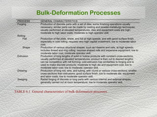
TABLE 6.1 General characteristics of bulk deformation processes.
PROCESS GENERAL CHARACTERISTICS
Forging Production of discrete parts with a set of dies; some finishing operations usually
necessary; similar parts can be made by casting and powder-metallurgy techniques;
usually performed at elevated temperatures; dies and equipment costs are high;
moderate to high labor costs; moderate to high operator skill.
Rolling
Flat Production of flat plate, sheet, and foil at high speeds, and with good surface finish,
especially in cold rolling; requires very high capital investment; low to moderate labor
cost.
Shape Production of various structural shapes, such as I-beams and rails, at high speeds;
includes thread and ring rolling; requires shaped rolls and expensive equipment; low to
moderate labor cost; moderate operator skill.
Extrusion Production of long lengths of solid or hollow products with constant cross-sections,
usually performed at elevated temperatures; product is then cut to desired lengths;
can be competitive with roll forming; cold extrusion has similarities to forging and is
used to make discrete products; moderate to high die and equipment cost; low to
moderate labor cost; low to moderate operator skill.
Drawing
Swaging
Production of long rod, wire, and tubing, with round or various cross-sections; smaller
cross-sections than extrusions; good surface finish; low to moderate die, equipment
and labor costs; low to moderate operator skill.
Radial forging of discrete or long parts with various internal and external shapes;
generally carried out at room temperature; low to moderate operator skill.
2. Impression-Die Forging
FIGURE 6.14 Schematic illustration of stages in impression-die forging. Note the formation
of flash, or excess material that is subsequently trimmed off.
4. Classification
Name Characters Cost Skill
Forging
Production of discrete parts with
dies
High High skill
Rolling (Flat) Flat plate, sheet, foil in long length High Equipment cost Low skill
Rolling (shape) Various structural shapes, I-beam Expensive Equipment Moderate
Extrusion
Long length of solid or hollow
products with constant cross-
section.
Moderate to high die and
equipment cost
Moderate
Drawing Production of long rod and wire Moderate cost Low skill
Swaging
Radial forging of discrete or long
parts with various internal and
external shapes; generally carried
out at room temperature;
Moderate cost
low to
moderate
operator
skill.
Bulk-Deformation Processes
5. Grain Flow Lines
FIGURE 6.2 Grain flow lines in
upsetting a solid steel cylinder at
elevated temperatures. Note the
highly inhomogenous deformation
and barreling. The different shape
of the bottom, section of the
specimen (as compared with the
top) results from the hot specimen
resting on the lower, cool die
before deformation proceeded.
The bottom surface was chilled;
thus it exhibits greater strength
and hence deforms less than the
top surface. Source: J. A. Schey et
al., IIT Research Institute.
6. Finite Element Simulation
FIGURE 6.11 Plastic
deformation in forging as
predicted by the finite-
element method of analysis.
Source: Courtesy of
Scientific Forming, Inc.
7. Plastic Deformation in Plane Strain
FIGURE 6.13 Examples of plastic
deformation processes in plane strain,
showing the h/L ratio. (a) Indenting with
flat dies. This operation is similar to
cogging, shown in Fig. 6.19. (b)
Drawing or extrusion of strip with a
wedge-shaped die, described in Sections
6.4 and 6.5. (c) Ironing; see also Fig.
7.54. (d) Rolling, described in Section
6.3. As shown in Fig. 6.12, the larger the
h/L ratio, the higher the die pressure
becomes. In actual processing, however,
the smaller this ratio, the greater is the
effect of friction at the die-workpiece
interfaces. The reason is that contact
area, and hence friction, increases with a
decreasing h/L ratio.
8. Impression-Die Forging
FIGURE 6.14 Schematic illustration of stages in impression-die forging. Note the
formation of flash, or excess material that is subsequently trimmed off.
Analysis
Simple shapes, without flash
Simple shapes, with flash
Complex shapes, with flash
3-5
5-8
8-12
F = (Kp)(Yf)(A)
TABLE 6.2 Range of Kp values in Eq. (6.21) for impression-die forging.
9. Load-Stroke Curve in Closed-Die Forging
FIGURE 6.15 Typical load-
stroke curve for closed-die
forging. Note the sharp increase in
load after the flash begins to form.
In hot-forging operations, the
flash requires high levels of
stress, because it is thin-that is, it
has a small h-and cooler than the
bulk of the forging. Source: After
T. Altan.
10. Heading
FIGURE 6.17 Forging heads on
fasteners such as bolts and rivets.
These processes are called heading.
Piercing Operations
FIGURE 6.18 Examples of piercing
operations.
11. Cogging Operation
FIGURE 6.19 Schematic illustration of a cogging operation on a rectangular bar. With
simple tools, the thickness and cross-section of a bar can be reduced by multiple cogging
operations. Note the barreling after cogging. Blacksmiths use a similar procedure to reduce
the thickness of parts in small increments by heating the workpiece and hammering it
numerous times.
12. Roll Forging Operation
FIGURE 6.20 Schematic illustration of a roll forging (cross-rolling) operation. Tapered leaf
springs and knives can be made by this process with specially designed rolls. Source: After
J. Holub.
13. Manufacture of Spherical Blanks
FIGURE 6.21 Production of steel balls for bearings
by the skew-rolling process. Balls for bearings can
also be made by the forging process shown in Fig.
6.22.
FIGURE 6.22 Production of steel
balls by upsetting of a cylindrical
blank. Note the formation of flash.
The balls are subsequently ground
and polished for use as ball
bearings and in other mechanical
components.
14. Internal Defects In Forging
FIGURE 6.24 Internal defects produced in a forging because of an oversized billet. The die
cavities are filled prematurely, and the material at the center of the part flows past the filled
regions as deformation continues.
FIGURE 6.23 Laps
formed by buckling of
the web during
forging.
15. Defect Formation In Forging
FIGURE 6.25 Effect of fillet radius on defect formation in forging. Small fillets (right side
of drawings) cause the defects. Source: Aluminum Company of America.
16. Forging A Connecting Rod
FIGURE 6.26 Stages in forging a connecting rod for an internal combustion engine. Note
the amount of flash that is necessary to fill the die cavities properly.
17. Features Of A Forging Die
FIGURE 6.27 Standard terminology for various features of a typical forging die.
Hot-Forging Temperature Ranges
Metal C F Metal C F
Aluminum alloys
Copper alloys
Nickel alloys
400-450
625-950
870-1230
750-850
1150-1750
1600-2250
Alloy steels
Titanium alloys
Refractory alloys
925-1260
750-795
975-1650
1700-2300
1400-1800
1800-3000
TABLE 6.3 Hot-forging temperature ranges for various metals.
18. Presses Used In Metalworking
FIGURE 6.28 Schematic illustration of various types of presses used in metalworking. The
choice of the press is an important factor in the overall operation.
22. Thread Rolling
Bulk deformation process used to form threads on cylindrical
parts by rolling them between two dies
Most important commercial process for mass producing bolts
and screws
|Performed by cold working in thread rolling machines
|Advantages over thread cutting (machining):
Higher production rates
Better material utilization
Stronger threads due to work hardening
Better fatigue resistance due to compressive stresses
introduced by rolling
24. •The thread is formed by the axial flow of material in the work piece.
• The grain structure of the material is not cut, but is distorted to follow the thread form.
• Rolled threads are produced in a single pass at speeds far in excess of those used to
cut
threads.
• The resultant thread is very much stronger than a cut thread. It has a greater resistance
to mechanical stress and an increase in fatigue strength. Also the surface is burnished and
work hardened.
26. Ring rolling used to reduce the wall
thickness and increase the diameter of a ring:
(1) start, and (2) completion of process
27.
28.
29. (a) Schematic illustration of
Ring-rolling operation.
Thickness reduction
results in an increase in
the part diameter.
(b) Examples of cross-
sections that can be
formed by ring-rolling
36. Transverse Rolling
•Using circular wedge rolls.
• Heated bar is cropped to length and
fed in transversely between rolls.
• Rolls are revolved in one direction.
37. Powder Rolling
Metal powder is introduced between the rolls and compacted into a
‘green strip’, which is subsequently sintered and subjected to further
hot- working and/ or cold working and annealing cycles.
Advantage :
- Cut down the initial hot- ingot breakdown step (reduced
capital investment).
- Economical - metal powder is cheaply produced during the
extraction process.
- Minimise contamination in hot- rolling.
- Provide fine grain size with a minimum of preferred
orientation.
45. Other CharacteristicsOther Characteristics
Residual stresses – produces:
Compressive residual stresses on the surfaces
Tensile stresses in the middle
Tolerances
Cold-rolled sheets: (+/- ) 0.1mm – 0.35mm
Tolerances much greater for hot-rolled plates
Surface roughness
Cold rolling can produce a very fine finish
Hot rolling & sand have the same range of surface finish
Gauge numbers – the thickness of a sheet is identified by a gauge number
46. Schematic Illustration of various roll arrangements : (a) two-
high; (b) three-high; (c) four-high; (d) cluster mill
48. مختلط اصطکاک
≥
〈
=
3
P
3
3
P
σ
µ
σ
σ
µµ
τ
P
i
),min( mKPi µτ =
21
1cos
2
1 mm
m
−+++
=
−π
µ
′〉
′′−
′−′
−′−+′
′〈
=
PP
)
3
Y
(
)(
exp1)
3
Y
(n
PP
s
s
Pm
PP
P
τ
τ
ττ
µ
τ
3
11 m
Ys
−−
=
′τ
)11(3
1cos
2
1 21
m
mm
Y
P
s −−
−+++
=
′
−π
)الف
)ب
( ج
49. غ نورديمتقارن ر)Asymetric Rolling(
[ ]{ }
)(2
)()(2)2)(2)((
12
2
1
12121212
hhRR
hhRRhhRhhRhh
L
lu
lulu
−++
−++−+−+−
=
lu
lu
eq
RR
RR
R
+
=
2
Ru
Rl
vu
vl
h2
h1
پا خنثی نقطهيينی
خنثی نقطه
باليی
x
R: بورق انحنا شعاعيرون
رونده
-زاو های سرعتيو بال ای ه
پاييهای سرعت ولی برابرند ن
.است متفاوت آنها خطی
eqR
x
hh
2
2 +=
50. غ نورديمتقارن ر)Asymetric Rolling(
0
2
)()(0 =
+−+−+−
+⇒=∑ dx
d
dx
dh
R
x
x
R
P
R
P
F lu
lulu
eql
l
u
u
x
σσ
ττσσ
∑ =+
−+−+⇒= 0)(
2
0
dx
d
hx
RR
PP
R
x
F
u
u
l
l
ul
eq
y
τττ
τ
0
12
)5(
6
)(
2
)(
22
0
2
=
−++−
−+++
−+⇒=∑
dx
d
dx
dh
R
xh
h
R
xh
R
P
R
Pxh
hM
lu
lu
eq
lulu
uu
u
l
l
σσ
σσ
ττσστ
uu dσσ +
ll dσσ +
ττ d+ τ
uσ
lσ
-ا دريدل به روش نيتنش اعمال ل
ب معادل کرنش برشی هایيشتری
.شود می اعمال
51. Drawing
FIGURE 6.62 Variables in
drawing round rod or wire.
FIGURE 6.63 Variation in strain and
flow stress in the deformation zone in
drawing. Note that the strain increases
rapidly toward the exit. The reason is that
when the exit diameter is zero, the true
strain reaches infinity. The point Ywire
represents the yield stress of the wire.
53. Swaging
FIGURE 6.71 Schematic illustration of the swaging
process: (a) side view and (b) front view. (c) Schematic
illustration of roller arrangement, curvature on the four
radial hammers (that give motion to the dies), and the radial
movement of a hammer as it rotates over the rolls.
FIGURE 6.72 Reduction of outer and inner diameters of
tubes by swaging. (a) Free sinking without a mandrel. The
ends of solid bars and wire are tapered (pointing) by this
process in order to feed the material into the conical die. (b)
Sinking on a mandrel. Coaxial tubes of different materials can
also be swaged in one operation.
54. Cross-Sections Produced By Swaging
FIGURE 6.73 (a) Typical cross-sections produced by swaging tube blanks with a constant wall
thickness on shaped mandrels. Rifling of small gun barrels can also be made by swaging, using a
specially shaped mandrel. The formed tube is then removed by slipping it out of the mandrel. (b) These
parts can also be made by swaging.