Downloaded 526 times


![Cylindrical Part Error
Reduction
0
10
20
30
40
50
60
P1 P2 P3 P4
PART CYCLE
0
0.2
0.4
0.6
0.8
1
1.2
1.4
1.6
RMSError[x0.001in.]
MAX
RMS
SSYYSSTTEEMM EERRRROORR TTHHRREESSHHOOLLDD
MAXIMALSHAPEERROR
[x0.001in.]](https://image.slidesharecdn.com/sheetmetal-140517020124-phpapp02/75/Sheet-metal-Forming-Process-41-2048.jpg)


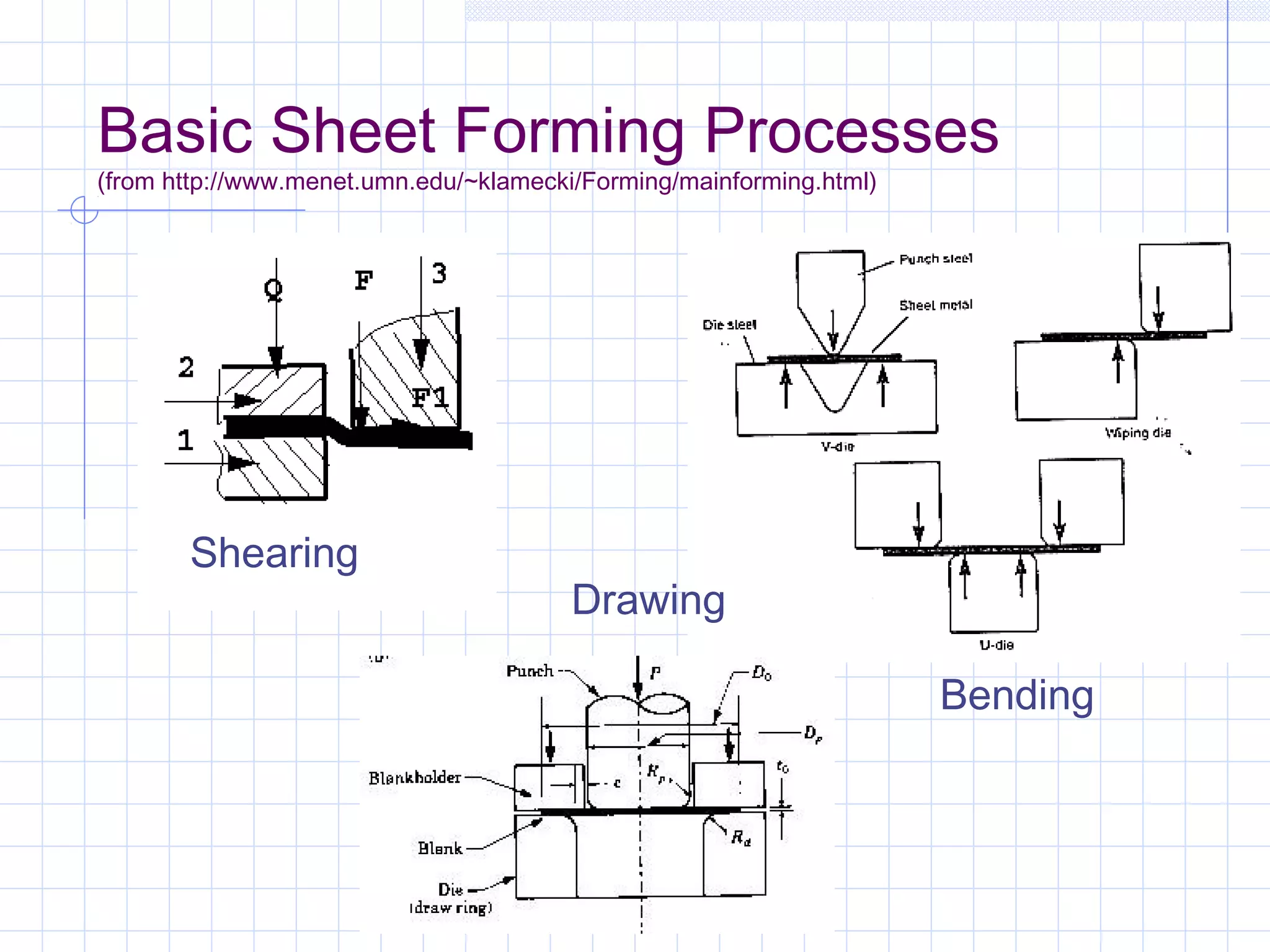
Sheet metal stamping was developed in the 1890s for mass production of bicycles, playing an important role in making interchangeable parts economical. Basic sheet forming processes include shearing, bending, drawing, and involve tools like shear presses, brake presses, and finger presses. Material selection is critical, balancing formability with strength, weight, cost, and corrosion resistance. Stretch forming allows tighter tolerances than stamping but is difficult for complex shapes. New developments include tailored blanks, binder force control, and quick die exchange. Alternative auto body materials offer cost and environmental benefits compared to steel.


