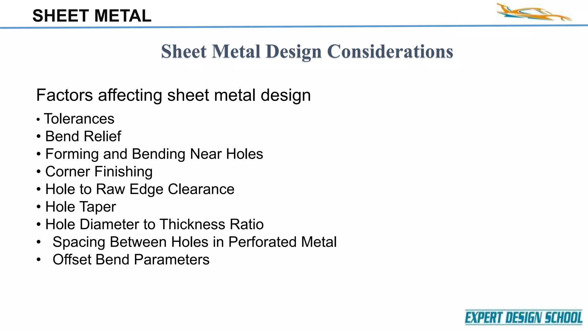
SHEET METAL
SHEET METAL DESIGN
SHEET METAL
CONTENT
• SHEET MEATL WORKING
a) Introduction
b) Standard size of sheet metal
c) Working condition
d) Common materials
• APPLICATION
• TYPES OF SHEET METAL PROCESSES
a) Shearing
b) Bending
c) Drawing
• DESIGN CONSIDERATION
• WELDING IN SHEET METAL
SHEET METAL
What is sheet metal working?
•Cutting and forming operations performed on relatively thin sheets of metal
•Operations usually performed as cold working
•Common materials: low carbon steel, aluminum or titanium
Classification sheet metal according to thickness
Type Thickness range(mm)
Stock 6+
Sheet metal 0.3 – 6
Foil >0.3
SHEET METAL
Standard sizes of sheet metal
SHEET METAL
• Gauge sizes are numbers that indicate the thickness of sheet metal, with a
higher gauge number referring to a thinner sheet.
• The equivalent thickness for each gauge size were developed based on the
weight of the sheet for a given material.
• The Manufacturer’s Standard Gauge provides the thickness for standard
steel, galvanized steel and stainless steel.
• The Brown & Sharpe Gauge known as the American Wire Gauge (AWG),
is used for non ferrous metals, such as Aluminum and Brass.
• The previous chart can be used to determine the equivalent sheet
thickness, in inches or mm, for a gauge number from the selected gauge
size standard.
SHEET METAL
COMMON SHEET METAL MATERIAL
• Stainless steel (SS) : SS304(most common), SS316, SS410, SS430.
• Aluminum (Al) : 1100-H14, 3003-H14, 5052-H32 and 6061-T6.
• Brass : It is alloy of copper and Zinc
SHEET METAL
APPLICATIONS
 Automobiles and trucks
 Airplane
 Railway cars and locomotive parts
 Farm and construction equipment
 Office furniture
 Computers and office equipments
SHEET METAL
SHEET METAL
Types of Sheet Metal Processes
1. Shearing
2. Bending
3. Drawing
SHEET METAL
SHEARING OPERATION
 Sheet metal cutting operation along a straight line between
two cutting edges
 Typically used to cut large sheets
SHEET METAL
BLANKING AND PUNCHING
a ) Blanking - sheet metal cutting to separate piece (called a blank) from surrounding stock
b) Punching - similar to blanking except cut piece is scrap, called a slug
SHEET METAL
Die size for blanking and punching
FOR BLANKING
 Blank punch diameter=Db-2c
 Blank die diameter = Db
FOR PUNCHING,
 Hole punch diameter=Dh
 Hole die diameter = Dh+2c
 Angular clearance of
0.25to 1.5
SHEET METAL
(a) SLOTTING : Punching operation that cut out an elongated or rectangular hole
(b) PERFORATING : Simultaneous punching of a pattern of holes in sheet metal
(c) NOTCHING : Cutting out a portion of metal from the side of the sheet
SHEET METAL
(a)TRIMMING
Cutting operation performed on form part to remove excess material.
(b)SHAVING
Shearing operation perform with very small clearance to obtain accurate
dimensional cut edge that are smooth and straight.
SHEET METAL
Bending
 Bending is defined as the straining of the sheet metal around a straight edge.
Metal below the neutral axis is compressed, while metal above the neutral axis is
stretched Metal on neutral axis neither stretched nor compressed.
SHEET METAL
Types of Sheet Metal Bending
V - bending
 For low production
 Performed on a brake press
 V-dies are simple and
inexpensive
Edge bending
 For high production
 Pressure pad required
 Dies are more complicated
and costly
SHEET METAL
Other Bending Operation
SHEET METAL
Increase in included angle of bent part relative to included angle of
forming tool after tool is removed.
 Reason
When bending pressure is removed, elastic energy remains in bent part,
causing it to recover partially toward its original shape.
SHEET METAL
Developed length
Developed length refers to the length of the unstretched fiber measured
over both bend and straight section of a bent sheet.
Factors affecting developed
length
•Tool geometry
•Effect of material properties
SHEET METAL
Formula for defining Developed length
L = (π/2*R+Y-FACTOR*T)*θ/90
Where,
π=3.145
R=Inside radius
T=Material thickness
θ=Bend angle
Y-Factor=0.50 (default)
SHEET METAL
Bending allowance
Bending allowance is method used to calculate the develop length of flat sheet
metal required to make a bend a specified radius and angle
BA= α*(R + Kt)
Y – FACTOR
Y-FACTOR is use for calculating the develop length.
Y=K*π/2
K-FACTOR
The k –factor is ratio between the inside radius of bend ,the neutral layer & sheet metal
thickness.
K=t/T
SHEET METAL
Drawing
It is Sheet metal forming process to make cup shaped, box shaped, or other
complex curved, hollow shaped parts.
 Sheet metal blank is positioned over die cavity and then punch pushes
metal into opening
 Products: beverage cans, ammunition shells, automobile body panels
 Also known as deep drawing (to distinguish it from wire and bar
drawing)
SHEET METAL
•High strength
•Good dimensional accuracy & surface finish
•Relatively low cost
•Wrinkling & tearing are typical limits to drawing
operations
•Techniques used to overcome these limitations
1. Draw beads
2. Vertical projections and matching groove
in the die and blank holder
•Trimming may be used to reach final
Advantages Disadvantages
SHEET METAL
Sheet Metal Design Considerations
• Tolerances
• Bend Relief
• Forming and Bending Near Holes
• Corner Finishing
• Hole to Raw Edge Clearance
• Hole Taper
• Hole Diameter to Thickness Ratio
• Spacing Between Holes in Perforated Metal
• Offset Bend Parameters
Factors affecting sheet metal design
SHEET METAL
Tolerances
The punched feature-to-feature tolerance for Sheet metal parts is +/-0.1mm, with a general
folding tolerance of +/-0.25mm
Bend Relief
• When a bend is close to an edge ,material may tear without bend relief.
• It is recommended to use rectangular relief.
• Minimum depth (D) of a bend relief should be equal to material thickness + radius of a bend.
• Depth of the relief should be greater than the radius of the bend.
• Minimum width (W) of a bend relief should be equal to 1.5 times the material thickness
• Width of the relief should be a material thickness or greater.
SHEET METAL
SHEET METAL
Forming and Bending Near Holes
• When a bend too close to a hole the hole will deformed.
• “Hole 1” shows a hole that has become teardrop shaped. To save cost of punching or drilling in a
secondary operation .
• Formula for a slot or hole < 25mm in diameter
• The minimum distance "D" = 2T + R
SHEET METAL
For Rectangular Holes
It is recommended that the minimum distance
from the edge of a rectangular hole to a bend should
be 3.5 times the material thickness.
For Circular Holes
It is recommended that the minimum
distance from the edge of a circular hole to
a bend should be 3 times the material
thickness.
D1 = Distance Between Hole and Bend
D2 = Distance Between Rectangular Holes and Bend
SHEET METAL
Spacing Between Holes in Perforated Metal
It is recommended that minimum distance between the holes in a perforated
metal should be equal to 1.2 times the material thickness.
SHEET METAL
Offset Bend Parameters
• It is also called as joggle, made up of two very short bends formed simultaneously. It is
used for overlap of a sheet.
• The A1 should be obtuse angles or right angles.
• The maximum H of an offset bend should be five times of the material thickness.
H = Offset Height
R = Bend Radius
A1 = Offset Bend Angle
SHEET METAL
Corner Finishing
• Standard Open Corner
A general-purpose corner for internal components where no finishing is required.
• Closed Corner Flush One Side
For external finished corners where no welding is required but a clean tight corner is needed.
• Standard Closed Corner
A general-purpose corner for component that requires a clean finish or fully welded finishing.
SHEET METAL
• Standard Closed Corner with Relief
A general-purpose corner for component that requires a clean finish and folding
relief to achieve tolerance and squareness.
SHEET METAL
Distance between Offset Bends and Extruded hole
The minimum recommended distance from the bend’s inside surface to the major
diameter of extrusion should be equal to 2.5 times the material thickness.
D = Distance between offset Bend to extruded Hole
SHEET METAL
Welding of sheet metal
• It is a very common process, used to seal the edges of bent parts.
• Commonly used weld processes are Metal Arc Welding (MIG), GAS Tungsten
Arc Welding (TIG) and resistance spot welding.
SHEET METAL
SHEET METAL
Types of welding joints
1.Butt joint
In Butt welded type, the parts lie in the same plane and are joined
at their edges.
2. Corner joint
The parts in a corner joint form a right angle and are joined at the
center of the angle.
3. Lap joint
Lap joint consists of two overlapping parts.
SHEET METAL
4. Tee-joint
In a Tee-joint, one joint is the right angle to the other joint in the approximate
shape of the letter “T”.
5. Edge joint
The parts in edge joint are parallel with at least one of their edges in common
and the joint is made at the common edge(s).
SHEET METAL
SHEET METAL

Sheet metal theory

  • 1.
  • 2.
    SHEET METAL CONTENT • SHEETMEATL WORKING a) Introduction b) Standard size of sheet metal c) Working condition d) Common materials • APPLICATION • TYPES OF SHEET METAL PROCESSES a) Shearing b) Bending c) Drawing • DESIGN CONSIDERATION • WELDING IN SHEET METAL
  • 3.
    SHEET METAL What issheet metal working? •Cutting and forming operations performed on relatively thin sheets of metal •Operations usually performed as cold working •Common materials: low carbon steel, aluminum or titanium Classification sheet metal according to thickness Type Thickness range(mm) Stock 6+ Sheet metal 0.3 – 6 Foil >0.3
  • 4.
  • 5.
    SHEET METAL • Gaugesizes are numbers that indicate the thickness of sheet metal, with a higher gauge number referring to a thinner sheet. • The equivalent thickness for each gauge size were developed based on the weight of the sheet for a given material. • The Manufacturer’s Standard Gauge provides the thickness for standard steel, galvanized steel and stainless steel. • The Brown & Sharpe Gauge known as the American Wire Gauge (AWG), is used for non ferrous metals, such as Aluminum and Brass. • The previous chart can be used to determine the equivalent sheet thickness, in inches or mm, for a gauge number from the selected gauge size standard.
  • 6.
    SHEET METAL COMMON SHEETMETAL MATERIAL • Stainless steel (SS) : SS304(most common), SS316, SS410, SS430. • Aluminum (Al) : 1100-H14, 3003-H14, 5052-H32 and 6061-T6. • Brass : It is alloy of copper and Zinc
  • 7.
    SHEET METAL APPLICATIONS  Automobilesand trucks  Airplane  Railway cars and locomotive parts  Farm and construction equipment  Office furniture  Computers and office equipments
  • 8.
  • 9.
    SHEET METAL Types ofSheet Metal Processes 1. Shearing 2. Bending 3. Drawing
  • 10.
    SHEET METAL SHEARING OPERATION Sheet metal cutting operation along a straight line between two cutting edges  Typically used to cut large sheets
  • 11.
    SHEET METAL BLANKING ANDPUNCHING a ) Blanking - sheet metal cutting to separate piece (called a blank) from surrounding stock b) Punching - similar to blanking except cut piece is scrap, called a slug
  • 12.
    SHEET METAL Die sizefor blanking and punching FOR BLANKING  Blank punch diameter=Db-2c  Blank die diameter = Db FOR PUNCHING,  Hole punch diameter=Dh  Hole die diameter = Dh+2c  Angular clearance of 0.25to 1.5
  • 13.
    SHEET METAL (a) SLOTTING: Punching operation that cut out an elongated or rectangular hole (b) PERFORATING : Simultaneous punching of a pattern of holes in sheet metal (c) NOTCHING : Cutting out a portion of metal from the side of the sheet
  • 14.
    SHEET METAL (a)TRIMMING Cutting operationperformed on form part to remove excess material. (b)SHAVING Shearing operation perform with very small clearance to obtain accurate dimensional cut edge that are smooth and straight.
  • 15.
    SHEET METAL Bending  Bendingis defined as the straining of the sheet metal around a straight edge. Metal below the neutral axis is compressed, while metal above the neutral axis is stretched Metal on neutral axis neither stretched nor compressed.
  • 16.
    SHEET METAL Types ofSheet Metal Bending V - bending  For low production  Performed on a brake press  V-dies are simple and inexpensive Edge bending  For high production  Pressure pad required  Dies are more complicated and costly
  • 17.
  • 18.
    SHEET METAL Increase inincluded angle of bent part relative to included angle of forming tool after tool is removed.  Reason When bending pressure is removed, elastic energy remains in bent part, causing it to recover partially toward its original shape.
  • 19.
    SHEET METAL Developed length Developedlength refers to the length of the unstretched fiber measured over both bend and straight section of a bent sheet. Factors affecting developed length •Tool geometry •Effect of material properties
  • 20.
    SHEET METAL Formula fordefining Developed length L = (π/2*R+Y-FACTOR*T)*θ/90 Where, π=3.145 R=Inside radius T=Material thickness θ=Bend angle Y-Factor=0.50 (default)
  • 21.
    SHEET METAL Bending allowance Bendingallowance is method used to calculate the develop length of flat sheet metal required to make a bend a specified radius and angle BA= α*(R + Kt) Y – FACTOR Y-FACTOR is use for calculating the develop length. Y=K*π/2 K-FACTOR The k –factor is ratio between the inside radius of bend ,the neutral layer & sheet metal thickness. K=t/T
  • 22.
    SHEET METAL Drawing It isSheet metal forming process to make cup shaped, box shaped, or other complex curved, hollow shaped parts.  Sheet metal blank is positioned over die cavity and then punch pushes metal into opening  Products: beverage cans, ammunition shells, automobile body panels  Also known as deep drawing (to distinguish it from wire and bar drawing)
  • 23.
    SHEET METAL •High strength •Gooddimensional accuracy & surface finish •Relatively low cost •Wrinkling & tearing are typical limits to drawing operations •Techniques used to overcome these limitations 1. Draw beads 2. Vertical projections and matching groove in the die and blank holder •Trimming may be used to reach final Advantages Disadvantages
  • 24.
    SHEET METAL Sheet MetalDesign Considerations • Tolerances • Bend Relief • Forming and Bending Near Holes • Corner Finishing • Hole to Raw Edge Clearance • Hole Taper • Hole Diameter to Thickness Ratio • Spacing Between Holes in Perforated Metal • Offset Bend Parameters Factors affecting sheet metal design
  • 25.
    SHEET METAL Tolerances The punchedfeature-to-feature tolerance for Sheet metal parts is +/-0.1mm, with a general folding tolerance of +/-0.25mm Bend Relief • When a bend is close to an edge ,material may tear without bend relief. • It is recommended to use rectangular relief. • Minimum depth (D) of a bend relief should be equal to material thickness + radius of a bend. • Depth of the relief should be greater than the radius of the bend. • Minimum width (W) of a bend relief should be equal to 1.5 times the material thickness • Width of the relief should be a material thickness or greater.
  • 26.
  • 27.
    SHEET METAL Forming andBending Near Holes • When a bend too close to a hole the hole will deformed. • “Hole 1” shows a hole that has become teardrop shaped. To save cost of punching or drilling in a secondary operation . • Formula for a slot or hole < 25mm in diameter • The minimum distance "D" = 2T + R
  • 28.
    SHEET METAL For RectangularHoles It is recommended that the minimum distance from the edge of a rectangular hole to a bend should be 3.5 times the material thickness. For Circular Holes It is recommended that the minimum distance from the edge of a circular hole to a bend should be 3 times the material thickness. D1 = Distance Between Hole and Bend D2 = Distance Between Rectangular Holes and Bend
  • 29.
    SHEET METAL Spacing BetweenHoles in Perforated Metal It is recommended that minimum distance between the holes in a perforated metal should be equal to 1.2 times the material thickness.
  • 30.
    SHEET METAL Offset BendParameters • It is also called as joggle, made up of two very short bends formed simultaneously. It is used for overlap of a sheet. • The A1 should be obtuse angles or right angles. • The maximum H of an offset bend should be five times of the material thickness. H = Offset Height R = Bend Radius A1 = Offset Bend Angle
  • 31.
    SHEET METAL Corner Finishing •Standard Open Corner A general-purpose corner for internal components where no finishing is required. • Closed Corner Flush One Side For external finished corners where no welding is required but a clean tight corner is needed. • Standard Closed Corner A general-purpose corner for component that requires a clean finish or fully welded finishing.
  • 32.
    SHEET METAL • StandardClosed Corner with Relief A general-purpose corner for component that requires a clean finish and folding relief to achieve tolerance and squareness.
  • 33.
    SHEET METAL Distance betweenOffset Bends and Extruded hole The minimum recommended distance from the bend’s inside surface to the major diameter of extrusion should be equal to 2.5 times the material thickness. D = Distance between offset Bend to extruded Hole
  • 34.
    SHEET METAL Welding ofsheet metal • It is a very common process, used to seal the edges of bent parts. • Commonly used weld processes are Metal Arc Welding (MIG), GAS Tungsten Arc Welding (TIG) and resistance spot welding.
  • 35.
  • 36.
    SHEET METAL Types ofwelding joints 1.Butt joint In Butt welded type, the parts lie in the same plane and are joined at their edges. 2. Corner joint The parts in a corner joint form a right angle and are joined at the center of the angle. 3. Lap joint Lap joint consists of two overlapping parts.
  • 37.
    SHEET METAL 4. Tee-joint Ina Tee-joint, one joint is the right angle to the other joint in the approximate shape of the letter “T”. 5. Edge joint The parts in edge joint are parallel with at least one of their edges in common and the joint is made at the common edge(s).
  • 38.
  • 39.