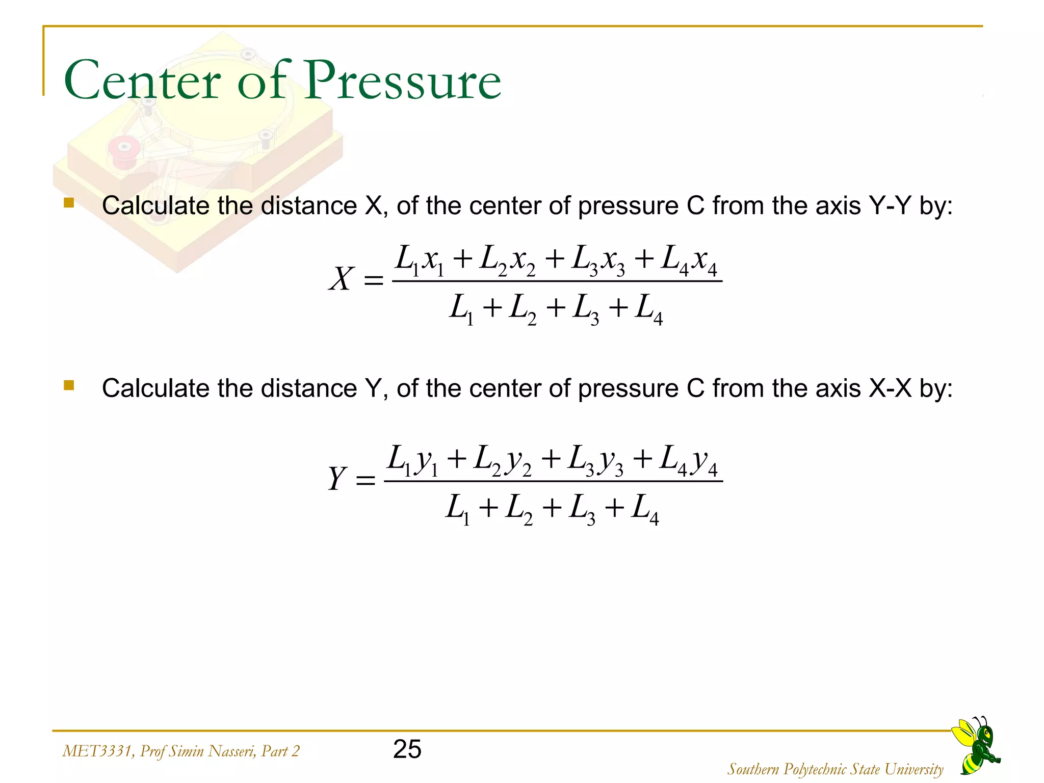
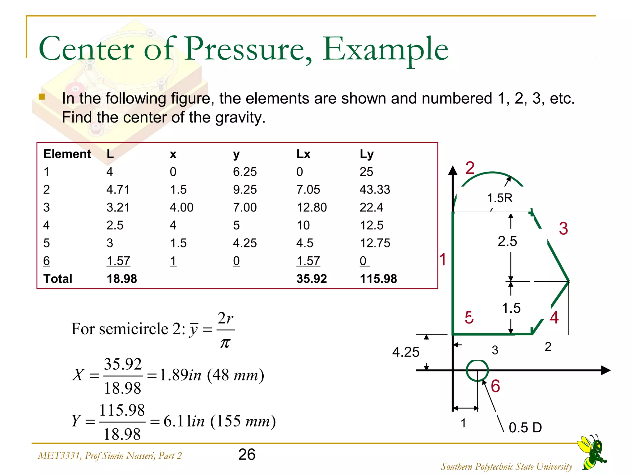
Okay, let's calculate the center of pressure step-by-step:
1) Calculate Lx, Ly for each element using the given dimensions
2) Sum Lx = 6.25 + 9.25 + 7 + 5 + 4.25 + 1 = 32.75
3) Sum Ly = 25 + 7.05 + 12.8 + 12.5 + 4.5 + 1.57 = 63.42
4) X (distance from axis YY) = Sum Lx / Sum L = 32.75 / 32.75 = 2.5
5) Y (distance from axis XX) = Sum Ly / Sum L = 63.42 / 32.75 = 1.94
this file is about the types of dies and also its manufacturing procedure.this is important for the industry and for the industrial and manufacturing engineering..are of this field is manufacturing engineering and die designalso for the blanking dies and punches
Press working terminology is described in a simple way to understand.Classification and Types are also explained in a simple way to understand by everyone.
sheet metal work ,die and punch.
it is generally useful for sheet metal operation.terminology of die and punch, types of die,types of punch,cutting force,method of reducing cutting force
Sheet metal characteristics – shearing, bending and drawing operations – Stretch forming operations – Formability of sheet metal – Test methods –special forming processes-Working principle and applications – Hydro forming – Rubber pad forming – Metal spinning– Introduction of Explosive forming, magnetic pulse forming, peen forming, Super plastic forming – Micro forming.
This chapter aims to provide basic backgrounds of different types of machining processes and highlights on an understanding of important parameters which affects machining of metals with their chip removals.
Metal cutting or Machining is the process of producing workpiece by removing unwanted material from a block of metal. in the form of chips. This process is most important since almost all the products get their final shape and size by metal removal. either directly or indirectly.
The major drawback of the process is loss of material in the form of chips. In this chapter. we shall have a fundamental understanding of the basic metal process.
This presentation contains various aspects of metal cutting like mechanics of chip formation, single point cutting tool, chip breakers, types of chips,etc
Simulation and experimental studies for lateral extrusion of square and penta...eSAT Journals
Abstract Recently, in different industries a surging trend has been observed in the demand of integral parts instead of assembled parts due to their increased strength. The components from lateral extrusion process are suitable for this purpose. Variations in load and flow direction of metal are greatly affected by the extruded geometry in this process. Keeping in view the above factors as an objective, an experimental die-punch set-up for lateral extrusion is designed and the process is simulated using finite element method both for estimation of load requirement and metal flow patterns. Experimental studies have been carried out to find the extrusion load and the direction of metal flow at different die geometry, taking lead as the billet material. The predictions both in extrusion load and the deformed configuration are in good agreement with the experiment qualitatively under different geometry conditions. Progressive flow of metal at different die geometry has also been studied. Index Terms: Die-punch, Finite element analysis, Forming load, Lateral extrusion, Metal flow pattern
IJRET : International Journal of Research in Engineering and Technology is an international peer reviewed, online journal published by eSAT Publishing House for the enhancement of research in various disciplines of Engineering and Technology. The aim and scope of the journal is to provide an academic medium and an important reference for the advancement and dissemination of research results that support high-level learning, teaching and research in the fields of Engineering and Technology. We bring together Scientists, Academician, Field Engineers, Scholars and Students of related fields of Engineering and Technology.
Safalta Digital marketing institute in Noida, provide complete applications that encompass a huge range of virtual advertising and marketing additives, which includes search engine optimization, virtual communication advertising, pay-per-click on marketing, content material advertising, internet analytics, and greater. These university courses are designed for students who possess a comprehensive understanding of virtual marketing strategies and attributes.Safalta Digital Marketing Institute in Noida is a first choice for young individuals or students who are looking to start their careers in the field of digital advertising. The institute gives specialized courses designed and certification.
for beginners, providing thorough training in areas such as SEO, digital communication marketing, and PPC training in Noida. After finishing the program, students receive the certifications recognised by top different universitie, setting a strong foundation for a successful career in digital marketing.
Biological screening of herbal drugs: Introduction and Need for
Phyto-Pharmacological Screening, New Strategies for evaluating
Natural Products, In vitro evaluation techniques for Antioxidants, Antimicrobial and Anticancer drugs. In vivo evaluation techniques
for Anti-inflammatory, Antiulcer, Anticancer, Wound healing, Antidiabetic, Hepatoprotective, Cardio protective, Diuretics and
Antifertility, Toxicity studies as per OECD guidelines
Acetabularia Information For Class 9 .docxvaibhavrinwa19
Acetabularia acetabulum is a single-celled green alga that in its vegetative state is morphologically differentiated into a basal rhizoid and an axially elongated stalk, which bears whorls of branching hairs. The single diploid nucleus resides in the rhizoid.
This slide is special for master students (MIBS & MIFB) in UUM. Also useful for readers who are interested in the topic of contemporary Islamic banking.
it describes the bony anatomy including the femoral head , acetabulum, labrum . also discusses the capsule , ligaments . muscle that act on the hip joint and the range of motion are outlined. factors affecting hip joint stability and weight transmission through the joint are summarized.
The simplified electron and muon model, Oscillating Spacetime: The Foundation...RitikBhardwaj56
Discover the Simplified Electron and Muon Model: A New Wave-Based Approach to Understanding Particles delves into a groundbreaking theory that presents electrons and muons as rotating soliton waves within oscillating spacetime. Geared towards students, researchers, and science buffs, this book breaks down complex ideas into simple explanations. It covers topics such as electron waves, temporal dynamics, and the implications of this model on particle physics. With clear illustrations and easy-to-follow explanations, readers will gain a new outlook on the universe's fundamental nature.
Exploiting Artificial Intelligence for Empowering Researchers and Faculty, In...Dr. Vinod Kumar Kanvaria
Exploiting Artificial Intelligence for Empowering Researchers and Faculty,
International FDP on Fundamentals of Research in Social Sciences
at Integral University, Lucknow, 06.06.2024
By Dr. Vinod Kumar Kanvaria
Read| The latest issue of The Challenger is here! We are thrilled to announce that our school paper has qualified for the NATIONAL SCHOOLS PRESS CONFERENCE (NSPC) 2024. Thank you for your unwavering support and trust. Dive into the stories that made us stand out!
A Strategic Approach: GenAI in EducationPeter Windle
Artificial Intelligence (AI) technologies such as Generative AI, Image Generators and Large Language Models have had a dramatic impact on teaching, learning and assessment over the past 18 months. The most immediate threat AI posed was to Academic Integrity with Higher Education Institutes (HEIs) focusing their efforts on combating the use of GenAI in assessment. Guidelines were developed for staff and students, policies put in place too. Innovative educators have forged paths in the use of Generative AI for teaching, learning and assessments leading to pockets of transformation springing up across HEIs, often with little or no top-down guidance, support or direction.
This Gasta posits a strategic approach to integrating AI into HEIs to prepare staff, students and the curriculum for an evolving world and workplace. We will highlight the advantages of working with these technologies beyond the realm of teaching, learning and assessment by considering prompt engineering skills, industry impact, curriculum changes, and the need for staff upskilling. In contrast, not engaging strategically with Generative AI poses risks, including falling behind peers, missed opportunities and failing to ensure our graduates remain employable. The rapid evolution of AI technologies necessitates a proactive and strategic approach if we are to remain relevant.
1. 1
Die Design
Part 2-Cutting Operations
J5811 - Tool Design
(Based on notes of Prof Dr Simin Nasseri,
Southern Polytechnic State University)
Sources:
Handbook of Die Design, Suchy
Sheet Metal forming Knowledge base, SME
Fundamentals of Tool Design, SME
2. 2MET3331, Prof Simin Nasseri, Part 2
Southern Polytechnic State University
Summary:
Die-cutting operations
Clearance in sheet metal cutting
Piercing die design
Blanking die design
Compound blanking & piercing
Design elements
Die block general design
Center of pressure
Peak cutting force
Stripping Force
Press Tonnage
Reducing Cutting Forces
3. 3MET3331, Prof Simin Nasseri, Part 2
Southern Polytechnic State University
Die Cutting Operation
Cutting and forming operations performed on relatively
thin sheets of metal
Thickness of sheet metal = 0.4 mm (1/64 in) to 6 mm (1/4
in)
Thickness of plate stock > 6 mm
Operations usually performed as cold working
Thickness= 0.4 to 6 mm (1/64 to 1/4 in)
4. 4MET3331, Prof Simin Nasseri, Part 2
Southern Polytechnic State University
Die Cutting Operation
Punching (Piercing): round punch cuts a hole in the work material.
The material (slug) cut from the sheetmetal is often scrap.
Blanking: differs from piercing only in that the part cut from the
work material is usable.
Blanking Punching or Piercing
5. 5MET3331, Prof Simin Nasseri, Part 2
Southern Polytechnic State University
Die Cutting Operation
Lancing: combines bending and cutting along a line in the work
material, leaving a bent portion or tab attached to the work
material.
Lancing
6. 6MET3331, Prof Simin Nasseri, Part 2
Southern Polytechnic State University
Die Cutting Operation
Notching: cuts off various shapes from the edge of the
workpiece material (a blank or a part).
7. 7MET3331, Prof Simin Nasseri, Part 2
Southern Polytechnic State University
Die Cutting Operation
Cut-off: achieves complete separation of the work material by
cutting it along straight or curved line.
Shaving: secondary shearing or cutting operation in which the
surface of a previously cut edge of a workpiece is finished or
smoothed (punch and die clearance is small).
Cut-off
8. 8MET3331, Prof Simin Nasseri, Part 2
Southern Polytechnic State University
Die Cutting Operation
Shearing of sheet metal
between two cutting
edges: (1) just before the
punch contacts work; (2)
punch begins to push into
work, causing plastic
deformation;
9. 9MET3331, Prof Simin Nasseri, Part 2
Southern Polytechnic State University
Die Cutting Operation
Shearing of sheet metal between two cutting edges: (3) punch
compresses and penetrates into work causing a smooth cut surface;
(4) fracture is initiated at the opposing cutting edges which separates
the sheet.
10. 10MET3331, Prof Simin Nasseri, Part 2
Southern Polytechnic State University
Clearance in Sheet Metal Cutting
Die size determines blank size Db
Punch size determines hole size Dh
c = clearance
Distance between punch cutting
edge and die cutting edge:
Depends on hardness and
thickness of materials
Thickness of metal c
Typical values range between
4% and 8% of stock thickness
11. 11MET3331, Prof Simin Nasseri, Part 2
Southern Polytechnic State University
Punching-die Design
Single-station
piercing die: A
complete press tool
for cutting two holes
in work material at
one stroke of the
press.
ngle dimple Single dimple (clean hole bottom) Double dimple clean hole top & bottom
12. 12MET3331, Prof Simin Nasseri, Part 2
Southern Polytechnic State University
Punching-die Design
A punch holder mounted to the upper shoe holds
the punch (guided by bushings inserted in the stripper).
A sleeve, or quill, encloses the punch to prevent
its buckling under pressure.
1. Top die shoe
2. Bottom die shoe
3. Guide plate
4. Top back-up block
5. Bottom back-up block
6. Guide pin
7. Punch
8. Punch holder with adjusting plate
9. V-Ring plate
10. Guide bushing
11. Adjusting plate
12. Punch retainer with adjusting plate
13. Ejector
14. Die
15. Piercing punch holder
16. Guide bushing
13. 13MET3331, Prof Simin Nasseri, Part 2
Southern Polytechnic State University
Blanking-die Design
The piercing punch is replaced by the blanking punch.
There are two types of blanking dies:
1- Simple or conventional blanking die
2- Inverted blanking die
14. 14MET3331, Prof Simin Nasseri, Part 2
Southern Polytechnic State University
1- Simple Blanking Die
Die is mounted to the lower shoe and punch is mounted to the
upper shoe.
Drop-through
design: finished
blanks drop
through the die.
Angular clearance
in needed to
remove the part.
15. 15MET3331, Prof Simin Nasseri, Part 2
Southern Polytechnic State University
2- Inverted Blanking Die
Used for producing larger
blanks,
The die is mounted to the upper
shoe,
The punch is mounted to the
lower shoe,
No need for angular clearance
as part is removed by hand.
The spring-loaded stripper is
mounted on the lower shoe
(travels upward in stripping the
stock from the punch fastened
to the lower shoe).
4th
ed, page 363
die die
rod
punch
16. 16MET3331, Prof Simin Nasseri, Part 2
Southern Polytechnic State University
2- Inverted Blanking Die
On the upstroke of the ram, the upper end of the knockout
rod strikes the arm on the press frame, which forces the
lower end of the rod downward, through the die.
It ejects the finished blank from the die cavity
Backing
plate
Die
An arm of the press frame
Knockout rod
Backing
plate
Die
Finished blank
upstroke
Part removal:
17. 17MET3331, Prof Simin Nasseri, Part 2
Southern Polytechnic State University
Compound Blanking & Piercing Die
A compound blanking and piercing
die is used to pierced blanks, eg a
washer.
Here both piercing punch and the
blanking punch are attached to the
upper-die shoe.
The piercing punch contacts the
material slightly ahead of the
blanking die.
The center hole is cut and outer
diameter trimmed in a single-die
station in one press stroke.
The material is usually 0.015 in
(0.38 mm) cold-rolled steel strip.
18. 18MET3331, Prof Simin Nasseri, Part 2
Southern Polytechnic State University
Compound Blanking & Piercing Die
The sheet material is lifted off the blanking punch by a spring-
actuated stripper.
The blanks normally remains in the upper die, and is usually
removed by knockout (which occurs at the top of stroke).
No angular clearance is needed (results in simpler die
construction).
In some cases, a piercing punch is attached to the upper-die shoe and
the blanking punch to the lower-die shoe.
Disadvantage:
The part must be removed from the upper die at the top of each
stroke. In case of small parts, once knocked out of the upper die,
they may be ejected by a timed blast of air.
19. 19MET3331, Prof Simin Nasseri, Part 2
Southern Polytechnic State University
What type of
blanking die is
this? (Simple
or inverted)
Although the
finished blanks do
not drop through
the die, but the
main feature is that
the punch is
mounted to the
upper shoe and the
die to the bottom
shoe. So this is
a ....
So this seems to be a simple blanking die. Notice that there is a piercing
punch at the bottom as well. So this is in fact a compound blanking and
piercing die!
Test yourself!
21. 21MET3331, Prof Simin Nasseri, Part 2
Southern Polytechnic State University
Systems of Length, Area, & Force measurements
In North America, engineering calculations for stamping are carried out
using measurements based on the following units:
For length and thickness: Inch,
For shear and yield strength: Pounds per square inch or psi,
For press force: 2000 lb.
Throughout most of the world:
For length and thickness: Meter, centimeter and millimeter
For shear and yield strength: KPa (K N/m2
) or MPa
For press force: Tons or 1000kg (sometimes KN & MN).
22. 22MET3331, Prof Simin Nasseri, Part 2
Southern Polytechnic State University
Die Block General Design
Overall dimensions will be determined by:
Minimum wall thickness required for
strength,
by the space needed for screws and dowels
and for mounting the stripper plate.
Depends upon the
thickness of the stock
to be cut.
Die thickness per ton of pressure
Stock Die Stock Die
Thickness in (mm) Thickness in (mm)* Thickness in (mm) Thickness in (mm)
0.1 (2.5) 0.03 (0.8) 0.6 (15.2) 0.15 (3.8)
0.2 (5.1) 0.06 (1.5) 0.7 (17.8) 0.165 (4.19)
0.3 (7.6) 0.085 (2.2) 0.8 (20.3) 0.18 (4.6)
0.4 (10.2) 0.11 (2.8) 0.9 (22.9) 0.19 (4.8)
0.5 (12.7) 0.13 (3.3) 1.00 (25.4) 0.20 (5.1)
* For each ton per sq in of shear strength
24. 24MET3331, Prof Simin Nasseri, Part 2
Southern Polytechnic State University
Center of Pressure
Irregularity in the shape of a blank, may result in a bending moment
in the press ram and undesirable deflections and misalignment.
This is because the summation of shearing forces on one side of the
center of the ram may greatly exceed the forces on the other side.
Center of pressure= Center of gravity of the perimeter of the blank,
not the area
A point about which the summation of shearing forces will be
symmetrical.
Why is it important to find this point?
G
Perimeter of the blank The press tool will be designed so that the
center of the pressure will be on the central
axis of the press ram when the tool is
mounted in the press.
25. 25MET3331, Prof Simin Nasseri, Part 2
Southern Polytechnic State University
Center of Pressure
Calculate the distance X, of the center of pressure C from the axis Y-Y by:
1 1 2 2 3 3 4 4
1 2 3 4
L x L x L x L x
X
L L L L
+ + +
=
+ + +
Calculate the distance Y, of the center of pressure C from the axis X-X by:
1 1 2 2 3 3 4 4
1 2 3 4
L y L y L y L y
Y
L L L L
+ + +
=
+ + +
26. 26MET3331, Prof Simin Nasseri, Part 2
Southern Polytechnic State University
Center of Pressure, Example
In the following figure, the elements are shown and numbered 1, 2, 3, etc.
Find the center of the gravity.
3
4
2
5
6
1
0.5 D
2.5
1.5
3 2
1.5R
4.25
Element L x y Lx Ly
1 4 0 6.25 0 25
2 4.71 1.5 9.25 7.05 43.33
3 3.21 4.00 7.00 12.80 22.4
4 2.5 4 5 10 12.5
5 3 1.5 4.25 4.5 12.75
6 1.57 1 0 1.57 0
Total 18.98 35.92 115.98
2
For semicircle 2:
35.92
1.89 (48 )
18.98
115.98
6.11 (155 )
18.98
r
y
X in mm
Y in mm
π
=
= =
= = 1
27. 27MET3331, Prof Simin Nasseri, Part 2
Southern Polytechnic State University
Peak Cutting Force
Important for determining press size (tonnage)
Fs = Ss . L . t
Where
Fs = Shear force
Ss = shear strength of metal
L = length of cut edge
t = stock thickness
Ss ≈ 0.7 St
St = Tensile strength
(F = Stress x Area of material cut = σ. A)
Thickness t
Length of cut edge or L = perimeter
of this rectangular shape
28. 28MET3331, Prof Simin Nasseri, Part 2
Southern Polytechnic State University
Shear strength and
tensile strength of
various materials are
written in this table.
Peak Cutting Force
29. 29MET3331, Prof Simin Nasseri, Part 2
Southern Polytechnic State University
Stripping Force
A properly designed tool needs to have
a method for holding the work while the
punch is pulled back through the
material.
This stripping procedure can be either
by a fixed-bridge or spring-loaded
stripper.
Thinner material deforms easily when
punch is withdrawn from a hole, so the
spring loaded stripper should be used.
Length of cut edge or L = perimeter
of this rectangular shape
t
http://www.diesupplies.com/catalog/accessories/35bbr_a.html
30. 30MET3331, Prof Simin Nasseri, Part 2
Southern Polytechnic State University
Stripping Force
Stripping force depends on:
Type of material being cut,
Area of the cut,
Clearance between punch & die,
Spring position, etc.
Rough empirical equation:
F = 1.5L t
L and t are in in and F in ton.
F = 20,600L t
L and t are in mm and F in kN.
31. 31MET3331, Prof Simin Nasseri, Part 2
Southern Polytechnic State University
Press Tonnage
The sum of all the forces required to cut and form.
In many cases, the stripping forces must be added to the cutting force.
This is while the spring-
loaded stripper is used.
Because, the springs are
compressed while cutting
the material.
Any other spring forces
for forming, draw pads, etc
will have to be added.
Fixed or tunnel strippers
will keep the press load to
a minimum, but they will
not control the stock as
well as spring-loaded ones.
32. 32MET3331, Prof Simin Nasseri, Part 2
Southern Polytechnic State University
Reducing Cutting Forces
Cutting forces are characterized by very high forces exerted
for very short periods. It is desirable to reduce these forces.
The likelihood of design difficulties and outright tool failure
increases if:
we have punch contours of large perimeters,
we have many smaller punches,
high tonnage requirements are concentrated in a small
area.
33. 33MET3331, Prof Simin Nasseri, Part 2
Southern Polytechnic State University
Reducing Cutting Forces
Two methods reduce cutting forces and smooth the shock impact of heavy
loads:
1- Adding shear to the die or punch equal to one-third of the material
thickness reduces the tonnage required by 50% for that area being cut
with shear applied.
2- By adjusting the height of the punches so they differ in
length by one-third the material thickness. (they can
cut in sequence rather than all at once). This reduces
the tonnage to one-third!
35. 35MET3331, Prof Simin Nasseri, Part 2
Southern Polytechnic State University
Test yourself!
Name the major
components of this die
and mention how many
relative motions exist.
The entire die is actuated
by a mechanical press
that moves the die up
and down. The press is
also responsible for
feeding the material
through the die,
progressing it from one
station to the next with
each stroke.
Clicking on the picture
will open the
progressive die
animation.
36. 36MET3331, Prof Simin Nasseri, Part 2
Southern Polytechnic State University
Test yourself!
1. Relative motion of the stripper backup & guide pins with respect to the
lower shoe,
2. Relative motion of the stripper backup with respect to the upper shoe,
3. Relative motion of the smaller guide pins (for the workpiece) with respect
to the stripper,
4. Relative motion of the workpiece and the supporting guides (shown in
yellow) with respect to the lower shoe.