Download as PDF, PPTX


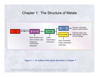
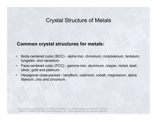


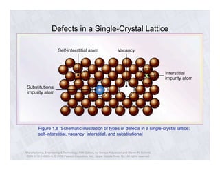


The document describes the structure of metals and their properties. It includes figures and outlines explaining common crystal structures of metals like body-centered cubic, face-centered cubic, and hexagonal close-packed. It also describes defects in crystal structures like vacancies and dislocations, and how plastic deformation occurs in metals through slip and twinning. The effects of processes like solidification, recovery, and recrystallization on grain size and mechanical properties are summarized.