Downloaded 173 times
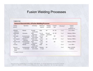
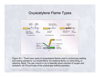
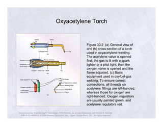
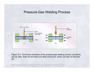
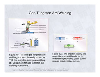
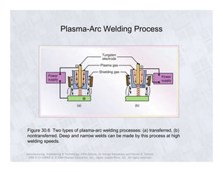

The document discusses various fusion welding processes and techniques. It describes oxyacetylene welding which uses different flame types to weld metals. Other fusion welding processes discussed include gas tungsten arc welding, plasma arc welding, shielded metal arc welding, and gas metal arc welding. The document also covers welding equipment, joint design, defects, testing, and residual stresses involved in different welding methods.