Downloaded 440 times


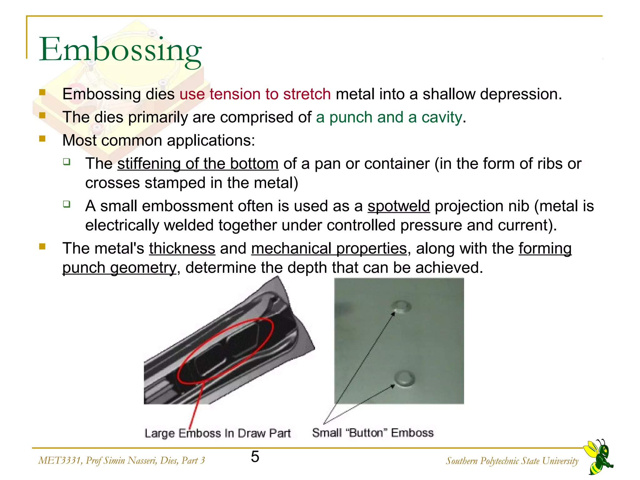
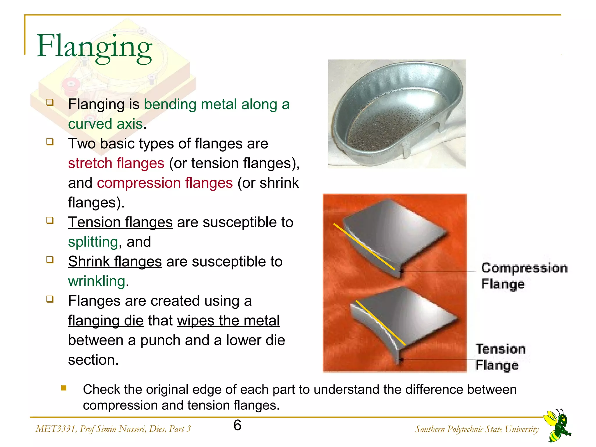
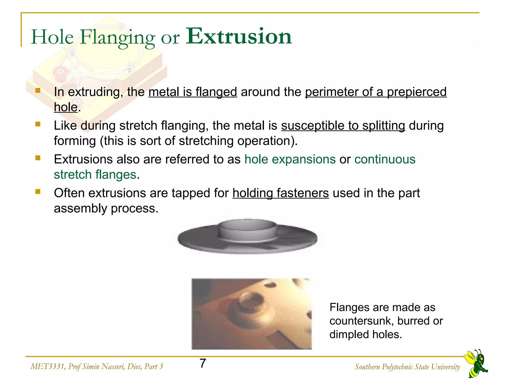


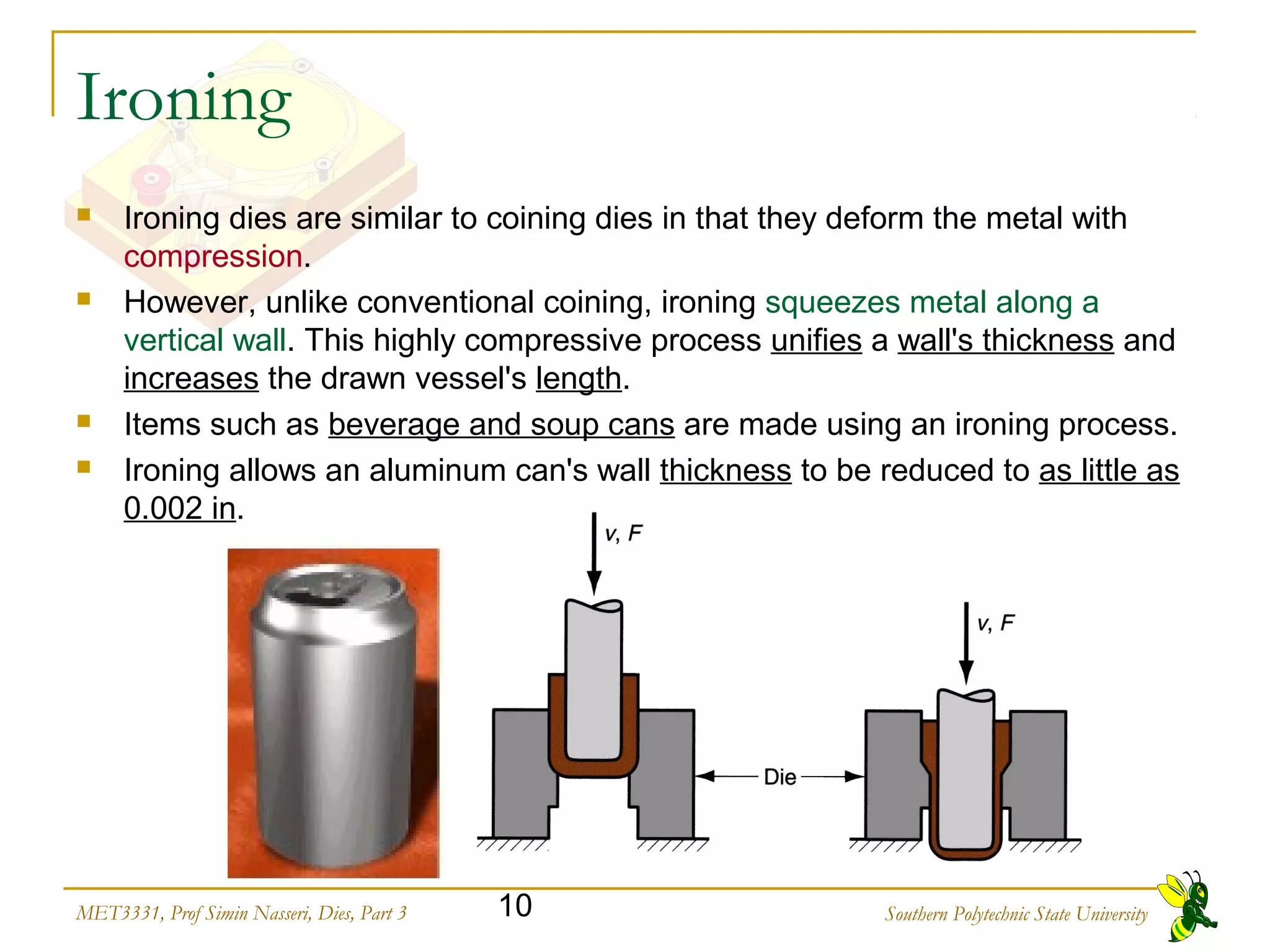

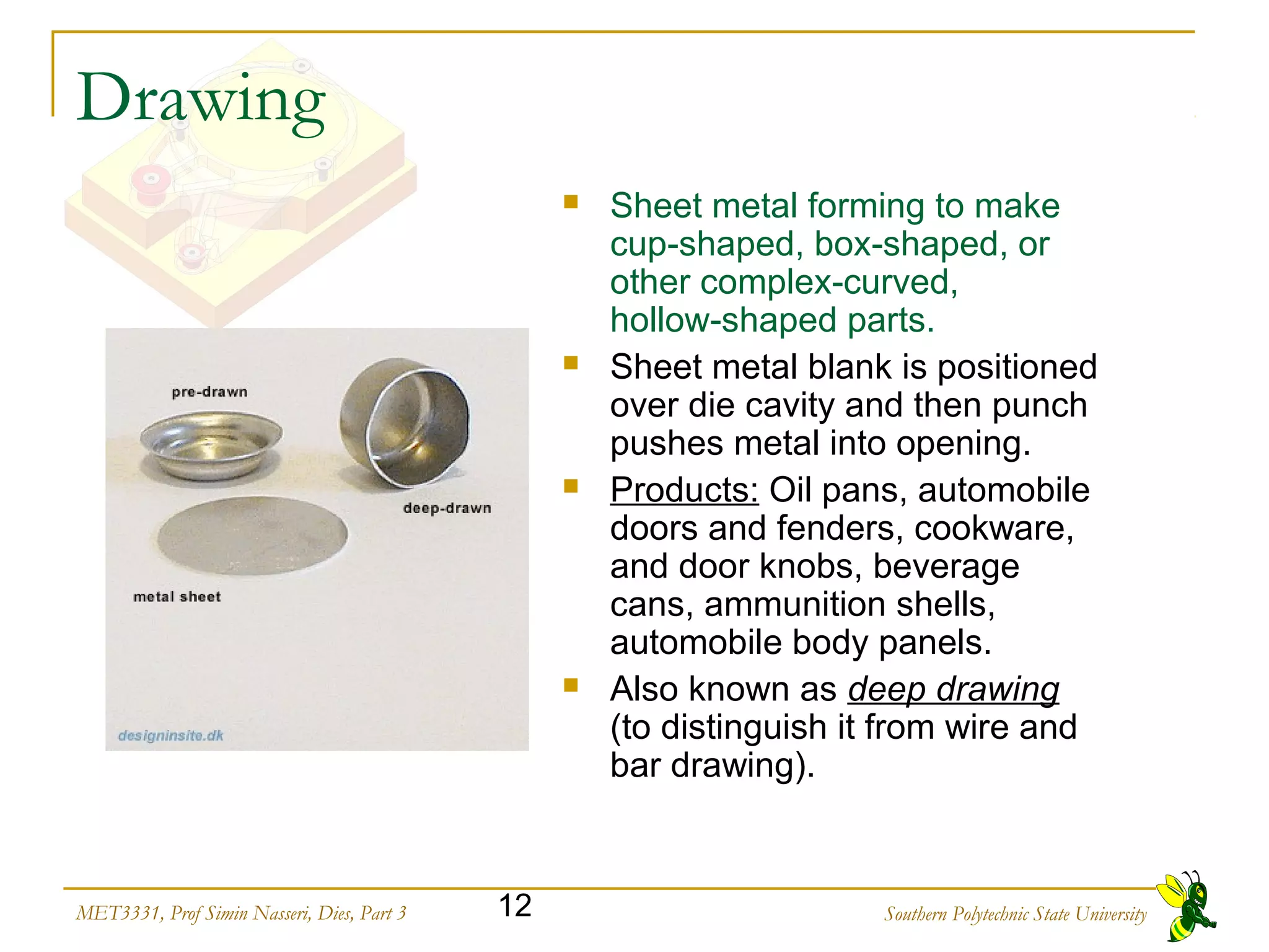


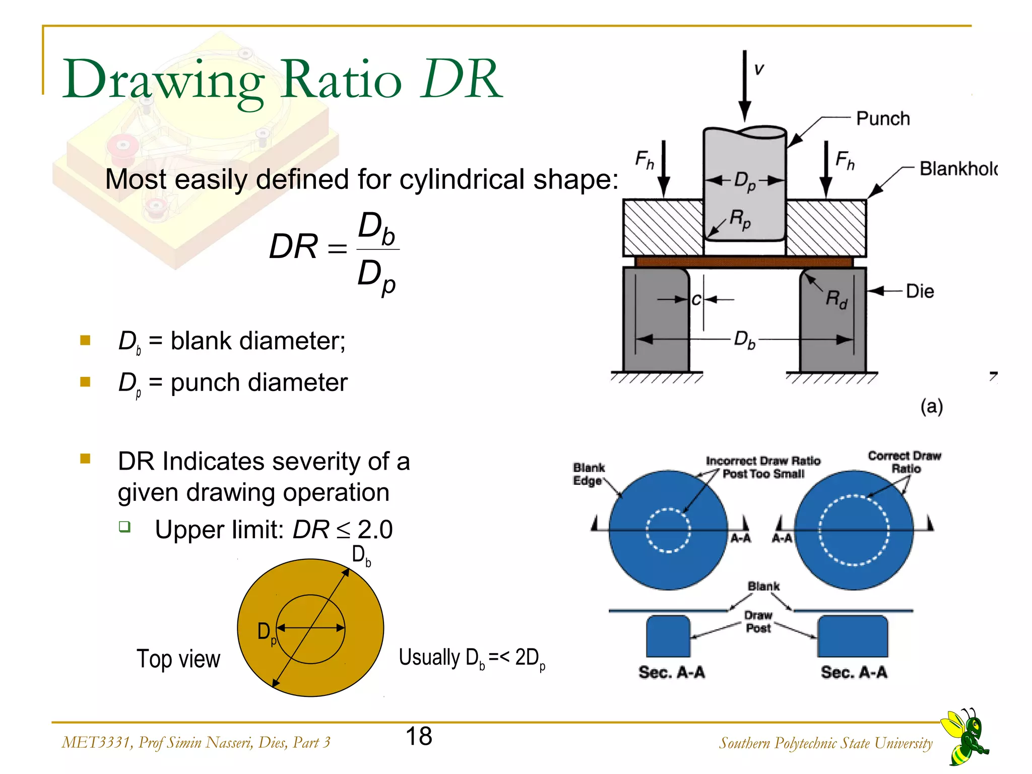
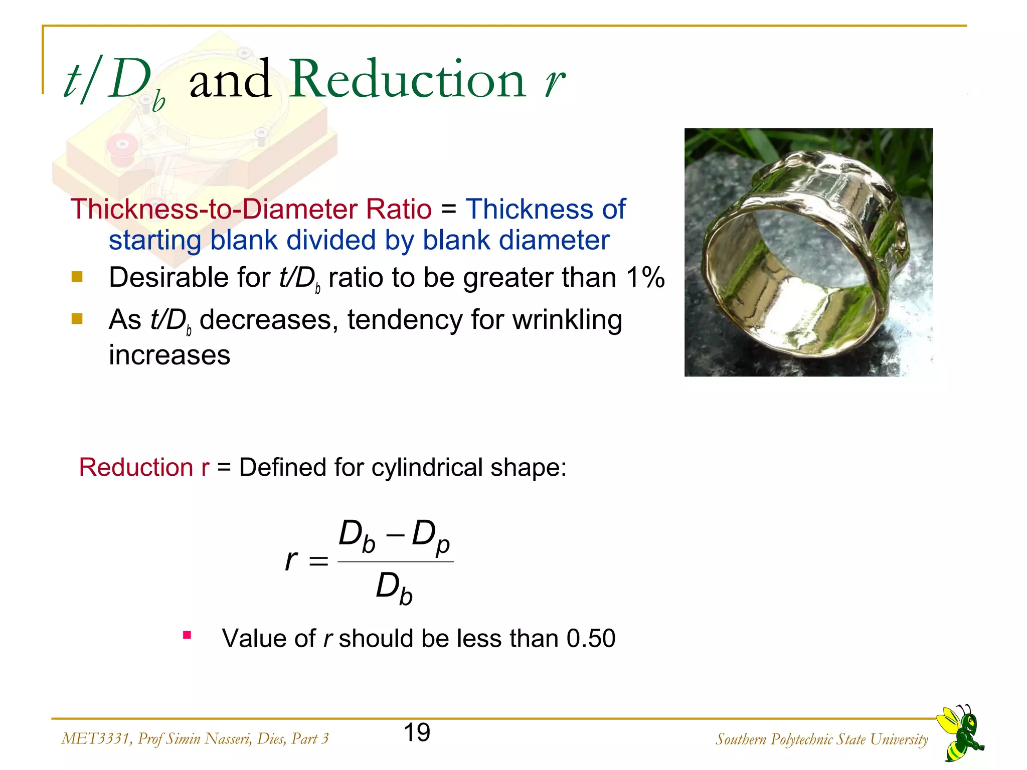


This document discusses various forming operations used in sheet metal working. It describes processes like bending, coining, embossing, flanging, hole flanging, beading and curling, ironing, and drawing. For each process, it provides details on how the process works, common applications, advantages and disadvantages. It also discusses considerations for forming die design like part material properties, number of required stampings, and clearance between the punch and die.


