Downloaded 348 times

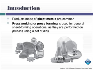
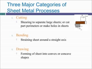
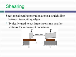
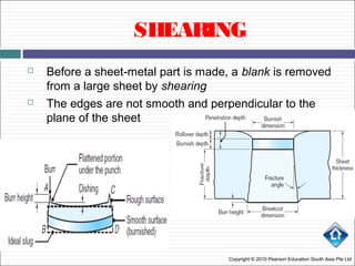
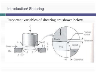
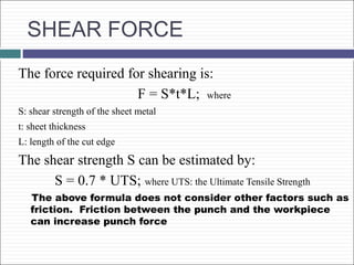
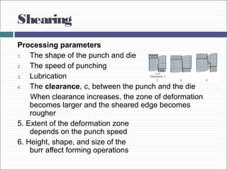
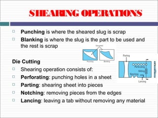
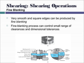
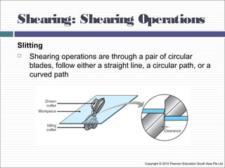
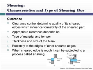
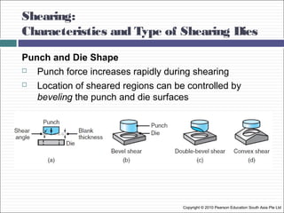
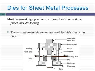
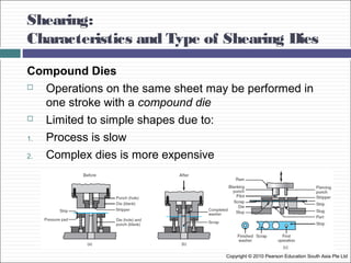
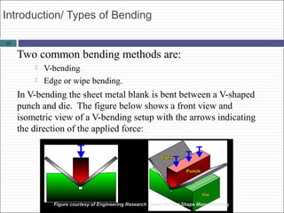
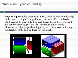
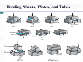
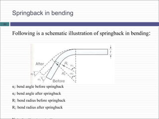
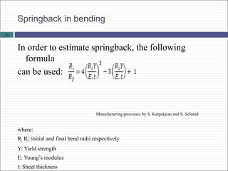
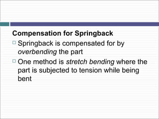
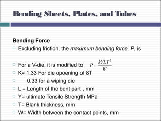
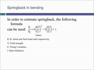
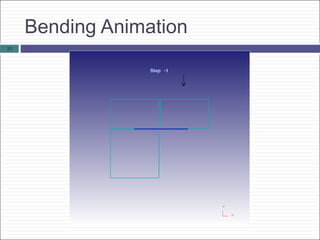
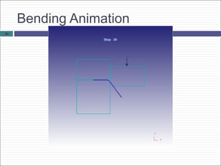

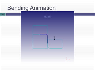
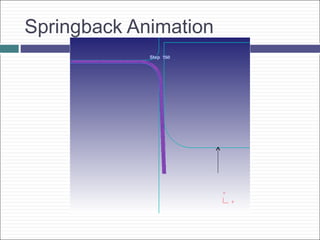
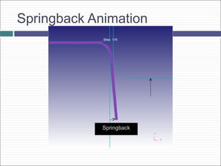
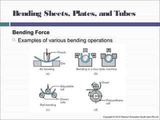
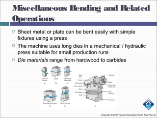
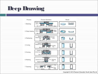


Sheet metal processes involve cutting, bending, and drawing operations. Shearing is the primary cutting operation used to cut sheet metal blanks from large sheets. It involves using a punch and die to cut along a straight line. Bending forms sheet metal by curving it around a straight axis and is done using V-bending or edge bending. Both cutting and bending can result in springback as the sheet tries to return to its original shape after forming. Process parameters like punch and die design, clearance, and lubrication affect the quality of cuts and bends in sheet metal fabrication.