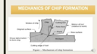
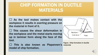
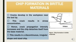
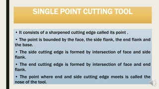
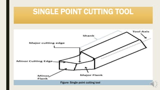
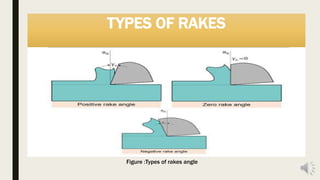
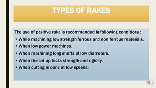
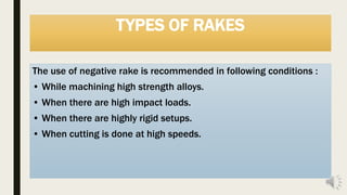
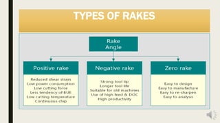
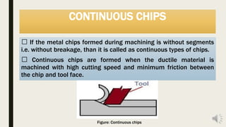
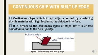
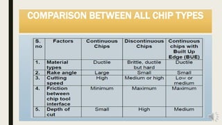
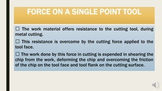
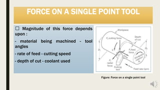
SlideShare a Scribd company logo
CHIP FORMATION & CUTTING
TOOL GEOMETRY
Md. Tarek Ur Rahman Erin
Sr. lecturer, Dept. of MTE, WUB
CONTENTS
■ 1. Introduction
■ 2. Mechanics of chip formation
■ 3. Single point cutting tool and its designation
■ 4. Methods of machining
■ 5. Types of chips
■ 6. Forces on single point cutting tool
■ 7. Chip Breakers
■ 8. Specific cutting pressure
INTRODUCTION
Metal cutting or machining is the process of producing
workpiece by removing unwanted material from a block of
metal, in the form of chips.
This process is most important because almost all
products get their final shape and size directly or indirectly
by machining.
Its major drawback is that in this process there is a lot of
material lost in the form of chips.
MECHANICS OF CHIP FORMATION
A wedge shaped tool is made to move relative to the workpiece.
As the tool makes contact with the workpiece it exerts pressure
on it resulting in compression of the metal near the tool tip.
This induces shear – type deformation within the metal and it
starts moving upward along the face of the tool.
As the tool advances this process of shearing goes on increasing
and material is removed.
MECHANICS OF CHIP FORMATION
CHIP FORMATION IN DUCTILE
MATERIALS
As the tool makes contact with the
workpiece it results in exerting pressure on
the material in front of it.
This causes the shear deformation in
the workpiece and the metal starts moving
up in laminar form along the face of the
tool.
This is also known as Pispannen’s
model of chip formation.
Figure : Chip formation in ductile
materials
CHIP FORMATION IN BRITTLE
MATERIALS
Cracks develop in the workpiece near
the tool tip.
This crack results in stress
concentration.
Hence, crack propagation intensity
increases and the chip detaches itself from
the base material.
This results in a discontinuous, irregular
shape and sized chip.
Figure : Chip formation in brittle
materials
SINGLE POINT CUTTING TOOL
• It consists of a sharpened cutting edge called its point .
• The point is bounded by the face, the side flank, the end flank and
the base.
• The side cutting edge is formed by intersection of face and side
flank.
• The end cutting edge is formed by intersection of face and end
flank.
• The point where end and side cutting edge meets is called the
nose of the tool.
SINGLE POINT CUTTING TOOL
Figure: Single point cutting tool
TOOL DESIGNATION
By designation or nomenclature of the tool we mean the
designation of the shape of the tool.
There are two systems widely used for tool designation :
• ASA System ( American standards association system ) or
ANSI System ( American National standards Institute system ).
• ORS ( Orthogonal Rake system)
In this discussion, we will know about ASA system.
TOOL DESIGNATION BY ASA SYSTEM
In this system the angles of
the tool face i.e. its slope,
are defined in two
orthogonal plane, one
parallel to and another
perpendicular to the axis of
cutting tool.
Figure :Tool designation by ASA system
TYPES OF RAKES
Figure :Types of rakes angle
TYPES OF RAKES
The use of positive rake is recommended in following conditions :
• While machining low strength ferrous and non ferrous materials.
• When low power machines.
• When machining long shafts of low diameters.
• When the set up lacks strength and rigidity.
• When cutting is done at low speeds.
TYPES OF RAKES
The use of negative rake is recommended in following conditions :
• While machining high strength alloys.
• When there are high impact loads.
• When there are highly rigid setups.
• When cutting is done at high speeds.
TYPES OF RAKES
METHODS OF MACHINING
In the cutting operation the tool is wedge shaped and has a
straight cutting edge.
Basically, there are two methods of metal cutting, depending
upon the arrangement of the cutting edge w.r.t. the direction of
relative tool work motion :
1. Orthogonal cutting
2. Oblique cutting
ORTHOGONAL CUTTING
Orthogonal cutting is a type of metal cutting in which the cutting
edge of wedge shape cutting tool is perpendicular to the direction of
tool motion.
In this cutting the cutting edge is wider than width of cut.
In this case the chip slides directly up the tool face.
Figure: Orthogonal cutting
OBLIQUE CUTTING
In oblique cutting, the cutting edge of the tool is set at an angle
other than 90˚ with respect to the direction of the velocity vector of
the tool.
In this case lateral direction of chip movement is obtained.
Figure: Oblique cutting
DIFFERENCE BETWEEN ORTHOGONAL AND
OBLIQUE CUTTING
CONTENTS
■ 1. Types of chips
■ 2. Forces on single point cutting tool
■ 3. Chip Breakers
■ 4. Specific cutting pressure
CHIPS AND ITS TYPES
The waste/dust material produced while machining any surface is
termed as chip. Depending on the workpiece material and the
cutting conditions, the following types of chip formation can be
distinguished.
Continuous chips
Discontinuous chips
Continuous chips with built up edges (BUE)
CONTINUOUS CHIPS
If the metal chips formed during machining is without segments
i.e. without breakage, than it is called as continuous types of chips.
Continuous chips are formed when the ductile material is
machined with high cutting speed and minimum friction between
the chip and tool face.
Figure: Continuous chips
CONTINUOUS CHIPS
The conditions which are responsible for the formation of
continuous types of chips are :
I. Ductile material like mild steel is used.
II. Bigger rake angle of the tool.
III. High cutting speed.
IV. Minimum friction between the chip and tool interface.
V. Small depth of cut.
CONTINUOUS CHIPS
• Advantages of Continuous Chips:
I. Better surface finish to the ductile material.
II. Less heat generation due to minimum friction between the tool
face and chip.
III. Low power consumption.
IV. Long tool life due to less wear and tear.
DISCONTINUOUS CHIPS
If the chips formed during machining process is not continuous
i.e. formed with breakage is called discontinuous chips.
Discontinuous types of chips are formed when hard and brittle
metals like brass, bronze and cast iron is machined.
DISCONTINUOUS CHIPS
Conditions which are responsible for the formation of discontinuous
chips are : Low feed rate.
I. Small rake angle of the tool.
II. High cutting speed.
III. High friction forces at the chip tool interface.
IV. Too much depth of cut.
DISCONTINUOUS CHIPS
Advantages :
The formation of discontinuous types of chips in brittle materials
provides good surface finish, increases the tool life and reduces the
consumption of power.
Disadvantages :
When discontinuous chips are formed in the ductile materials, the
workpiece result in poor surface finish and excessive wear and tear
of the tool takes place.
CONTINUOUS CHIP WITH BUILT UP EDGE
Continuous chips with built up edge is formed by machining
ductile material with high friction at the chip-tool interface.
It is similar to the continuous types of chips but it is of less
smoothness due to the built up edge.
Figure: Continuous chip with built up edge
FORMATION OF BUILT UP EDGE
• When the chip flows in upward direction there exist high friction in
between the interface of the chip and tool.
• Due to the high friction between the chip and tool a very intense
heat is generated at the nose of the tool.
• The compressed metal adjacent to the tool nose gets welded to it.
This compressed metal welded to the nose is called built up edge.
• Due to formation of the built up edge the rake angle of the tool
gets changed and so is the cutting force.
CONTINUOUS CHIP WITH BUILT UP EDGE
The factors which are responsible for promoting the
formation of the BUE chips are:
Excessive feed rate.
Small rake angle of the tool.
Low cutting speed.
Lack of coolant and this increase the friction between the chip
tool interfaces.
CONTINUOUS CHIP WITH BUILT UP EDGE
Advantages :
The making of the BUE has one advantage i.e. it protects the tool
from getting damaged from high friction and temperature
generated during machining process and hence the tool life
increases.
Disadvantages :
The formation of these types of chips results in rough surface finish,
change in the rake angle and cutting forces.
COMPARISON BETWEEN ALL CHIP TYPES
FORCE ON A SINGLE POINT TOOL
The work material offers resistance to the cutting tool, during
metal cutting.
This resistance is overcome by the cutting force applied to the
tool face.
The work done by this force in cutting is expended in shearing the
chip from the work, deforming the chip and overcoming the friction
of the chip on the tool face and tool flank on the cutting surface.
FORCE ON A SINGLE POINT TOOL
Magnitude of this force depends upon :
- material being machined - tool angles
- rate of feed - cutting speed
- depth of cut - coolant used
FORCE ON A SINGLE POINT TOOL
Magnitude of this force depends
upon :
- material being machined - tool
angles
- rate of feed - cutting speed
- depth of cut - coolant used
Figure: Force on a single point tool
CHIP BREAKERS
Continuous chips produced while machining ductile materials
often causes difficulties of handling because they occupy
considerable space and have sharp edges.
They may also be hot.
They also get entangled and start rotating with the job.
Hence, it is desirable to break these chips into short convenient
length for their proper disposal. This operation of chip breaking is
done by chip breakers.
CHIP BREAKERS
Chip breakers are classified as :
I. Groove type
II. Obstruction type
Figure: Groove type chip breakers Figure: Obstruction type chip breakers
CHIP BREAKERS
Advantages :
Ensure safety for operator.
Increase tool life.
Facilitate the removal of chips from cutting zone.
Reduce the cutting resistance and vibration, hence increase
machine performance.
Machined surface do not get spoiled by continuous chips.
Increase productivity (decrease time loss) – small chips take less
volume than continuous chip, so it does not need chip disposal as
frequent as continuous chip.
CHIP BREAKERS
Disadvantages of chip breaker :
Frequent chip braking and hitting at flank of tool may causes
harmful vibration.
Some cases the use of chip breaker causes the spoilage of
surface finish quality.
Heat and stress concentrated at sharp cutting edge, results the
rapid failure of cutting edge.
BIBLIOGRAPHY
A Text book of manufacturing technology by R.K. Rajput – Laxmi
publications.
A Text book of production engineering by P.C. Sharma – Chapter
no. 14 – S. Chand and company Limited, 2006 Edition, ISBN 81-
219-0421-8.
Manufacturing process II – Lecture by Dr. V.K. Jain Indian Institute
of technology, Kanpur.
Images from www.google.com
www.mecholic.com
www.mechanicalbooster.com
Thank You

More Related Content

What's hot

Chips formation
Chips formationChips formation
Chips formation
ankit singh
 
Metal cutting 2
Metal cutting  2Metal cutting  2
Metal cutting 2
Naman Dave
 
Rolling Process
Rolling ProcessRolling Process
Rolling Process
M Siva Kumar
 
Thermal aspects in machining
Thermal aspects in machiningThermal aspects in machining
Thermal aspects in machining
Prof.Mayur Modi
 
Sheet metal-forming-processes
Sheet metal-forming-processesSheet metal-forming-processes
Sheet metal-forming-processessahilslideshare
 
Rolling process
Rolling processRolling process
Rolling process
Pravinkumar
 
ppt on Forging process
ppt on Forging processppt on Forging process
ppt on Forging process
RAHUL DAS
 
Unit 3A3 - broaching
Unit 3A3 - broachingUnit 3A3 - broaching
Unit 3A3 - broaching
Mechbytes
 
Orthogonal & oblique cutting
Orthogonal & oblique cuttingOrthogonal & oblique cutting
Orthogonal & oblique cutting
Shivam Kumar
 
press tool, jigs & fixtures, gear and thread manufacturing,manufacturing pro...
 press tool, jigs & fixtures, gear and thread manufacturing,manufacturing pro... press tool, jigs & fixtures, gear and thread manufacturing,manufacturing pro...
press tool, jigs & fixtures, gear and thread manufacturing,manufacturing pro...
Prof.Mayur Modi
 
Single Point Cutting Tools
Single Point Cutting ToolsSingle Point Cutting Tools
Single Point Cutting Tools
GIRISH SURVE
 
Theory of Metal Cutting
Theory of Metal CuttingTheory of Metal Cutting
Theory of Metal Cutting
Kunduru Srinivasulu Reddy
 
Machining operations and machine tools
Machining operations and machine toolsMachining operations and machine tools
Machining operations and machine tools
Muhammad Muddassir
 
Machining Process
Machining ProcessMachining Process
Machining Process
Kunj Soni
 
Grinding wheel
Grinding wheel Grinding wheel
Grinding wheel
Amaresh Choudhary
 
Design Consideration For Casting
Design Consideration For CastingDesign Consideration For Casting
Design Consideration For Casting
Mohit Joon
 
Forging
ForgingForging
Forging
Bilalwahla
 
Shaper, slotter, planer
Shaper, slotter, planerShaper, slotter, planer
Shaper, slotter, planer
akashpatel281996
 

What's hot (20)

Chips formation
Chips formationChips formation
Chips formation
 
Metal cutting 2
Metal cutting  2Metal cutting  2
Metal cutting 2
 
Rolling Process
Rolling ProcessRolling Process
Rolling Process
 
Milling cutter
Milling cutterMilling cutter
Milling cutter
 
Thermal aspects in machining
Thermal aspects in machiningThermal aspects in machining
Thermal aspects in machining
 
Sheet metal-forming-processes
Sheet metal-forming-processesSheet metal-forming-processes
Sheet metal-forming-processes
 
Rolling process
Rolling processRolling process
Rolling process
 
ppt on Forging process
ppt on Forging processppt on Forging process
ppt on Forging process
 
Unit 3A3 - broaching
Unit 3A3 - broachingUnit 3A3 - broaching
Unit 3A3 - broaching
 
Orthogonal & oblique cutting
Orthogonal & oblique cuttingOrthogonal & oblique cutting
Orthogonal & oblique cutting
 
press tool, jigs & fixtures, gear and thread manufacturing,manufacturing pro...
 press tool, jigs & fixtures, gear and thread manufacturing,manufacturing pro... press tool, jigs & fixtures, gear and thread manufacturing,manufacturing pro...
press tool, jigs & fixtures, gear and thread manufacturing,manufacturing pro...
 
Single Point Cutting Tools
Single Point Cutting ToolsSingle Point Cutting Tools
Single Point Cutting Tools
 
Theory of Metal Cutting
Theory of Metal CuttingTheory of Metal Cutting
Theory of Metal Cutting
 
Machining operations and machine tools
Machining operations and machine toolsMachining operations and machine tools
Machining operations and machine tools
 
Machining Process
Machining ProcessMachining Process
Machining Process
 
Cutting tools
Cutting tools Cutting tools
Cutting tools
 
Grinding wheel
Grinding wheel Grinding wheel
Grinding wheel
 
Design Consideration For Casting
Design Consideration For CastingDesign Consideration For Casting
Design Consideration For Casting
 
Forging
ForgingForging
Forging
 
Shaper, slotter, planer
Shaper, slotter, planerShaper, slotter, planer
Shaper, slotter, planer
 

Similar to Chip formation & cutting tool geometry

Production technology Metal Cutting introduction
Production technology Metal Cutting introductionProduction technology Metal Cutting introduction
Production technology Metal Cutting introduction
Ahmedabad Institute Of Technology
 
Production engineering
Production engineeringProduction engineering
Production engineering
STAY CURIOUS
 
Metal cutting
Metal cuttingMetal cutting
Metal cutting
Aishik Roy Chaudhury
 
04 metal cutting(1)
04 metal cutting(1)04 metal cutting(1)
04 metal cutting(1)
Thulasikanth Vaddi
 
04metalcutting1 161019143042
04metalcutting1 16101914304204metalcutting1 161019143042
04metalcutting1 161019143042
manojkumarg1990
 
Metal cutting and Machining tools
Metal cutting and Machining toolsMetal cutting and Machining tools
Metal cutting and Machining tools
SHIVAM AGRAWAL
 
Unit1
Unit1Unit1
Metal cutting basics-min.docx
Metal cutting basics-min.docxMetal cutting basics-min.docx
Metal cutting basics-min.docx
ssuser72b8e8
 
4 types of chips (1)
4 types of chips (1)4 types of chips (1)
4 types of chips (1)
Anit Aggarwal
 
Metal removing process_IPE 305.pptx
Metal removing process_IPE 305.pptxMetal removing process_IPE 305.pptx
Metal removing process_IPE 305.pptx
IshmamTasnim
 
Unit-I Theory of Metal Cutting-1.pptx
Unit-I Theory of Metal Cutting-1.pptxUnit-I Theory of Metal Cutting-1.pptx
Unit-I Theory of Metal Cutting-1.pptx
Mohamedsulaiman53
 
THEORY OF METAL CUTTING.ppt
THEORY OF METAL CUTTING.pptTHEORY OF METAL CUTTING.ppt
THEORY OF METAL CUTTING.ppt
DineshKumar4165
 
Unit 1
Unit   1Unit   1
Unit 1
dinesh babu
 
Metal cutting 1
Metal cutting 1Metal cutting 1
Metal cutting 1
Naman Dave
 
machining and machine tool Unit 1&2
machining and machine tool Unit 1&2machining and machine tool Unit 1&2
machining and machine tool Unit 1&2
alakshendra pratap singh
 
MT-II UNIT I THEORY OF METAL CUTTING
MT-II UNIT I THEORY OF METAL CUTTINGMT-II UNIT I THEORY OF METAL CUTTING
MT-II UNIT I THEORY OF METAL CUTTING
Karthik R
 
metal cutting,manufacturing processes,Production Technology
 metal cutting,manufacturing processes,Production Technology metal cutting,manufacturing processes,Production Technology
metal cutting,manufacturing processes,Production Technology
Prof.Mayur Modi
 
1metalcutting-181227105337.pdf
1metalcutting-181227105337.pdf1metalcutting-181227105337.pdf
1metalcutting-181227105337.pdf
ANANTKUMARGUJAR
 
1 PPT Metal Cutting 30-04-2020.pdf
1 PPT Metal Cutting 30-04-2020.pdf1 PPT Metal Cutting 30-04-2020.pdf
1 PPT Metal Cutting 30-04-2020.pdf
ssuser823c58
 
Ppt ms2
Ppt ms2Ppt ms2

Similar to Chip formation & cutting tool geometry (20)

Production technology Metal Cutting introduction
Production technology Metal Cutting introductionProduction technology Metal Cutting introduction
Production technology Metal Cutting introduction
 
Production engineering
Production engineeringProduction engineering
Production engineering
 
Metal cutting
Metal cuttingMetal cutting
Metal cutting
 
04 metal cutting(1)
04 metal cutting(1)04 metal cutting(1)
04 metal cutting(1)
 
04metalcutting1 161019143042
04metalcutting1 16101914304204metalcutting1 161019143042
04metalcutting1 161019143042
 
Metal cutting and Machining tools
Metal cutting and Machining toolsMetal cutting and Machining tools
Metal cutting and Machining tools
 
Unit1
Unit1Unit1
Unit1
 
Metal cutting basics-min.docx
Metal cutting basics-min.docxMetal cutting basics-min.docx
Metal cutting basics-min.docx
 
4 types of chips (1)
4 types of chips (1)4 types of chips (1)
4 types of chips (1)
 
Metal removing process_IPE 305.pptx
Metal removing process_IPE 305.pptxMetal removing process_IPE 305.pptx
Metal removing process_IPE 305.pptx
 
Unit-I Theory of Metal Cutting-1.pptx
Unit-I Theory of Metal Cutting-1.pptxUnit-I Theory of Metal Cutting-1.pptx
Unit-I Theory of Metal Cutting-1.pptx
 
THEORY OF METAL CUTTING.ppt
THEORY OF METAL CUTTING.pptTHEORY OF METAL CUTTING.ppt
THEORY OF METAL CUTTING.ppt
 
Unit 1
Unit   1Unit   1
Unit 1
 
Metal cutting 1
Metal cutting 1Metal cutting 1
Metal cutting 1
 
machining and machine tool Unit 1&2
machining and machine tool Unit 1&2machining and machine tool Unit 1&2
machining and machine tool Unit 1&2
 
MT-II UNIT I THEORY OF METAL CUTTING
MT-II UNIT I THEORY OF METAL CUTTINGMT-II UNIT I THEORY OF METAL CUTTING
MT-II UNIT I THEORY OF METAL CUTTING
 
metal cutting,manufacturing processes,Production Technology
 metal cutting,manufacturing processes,Production Technology metal cutting,manufacturing processes,Production Technology
metal cutting,manufacturing processes,Production Technology
 
1metalcutting-181227105337.pdf
1metalcutting-181227105337.pdf1metalcutting-181227105337.pdf
1metalcutting-181227105337.pdf
 
1 PPT Metal Cutting 30-04-2020.pdf
1 PPT Metal Cutting 30-04-2020.pdf1 PPT Metal Cutting 30-04-2020.pdf
1 PPT Metal Cutting 30-04-2020.pdf
 
Ppt ms2
Ppt ms2Ppt ms2
Ppt ms2
 

More from Tarek Erin

2. Atomic, molecular, crytalline and amorphous structures for metals.pptx
2. Atomic, molecular, crytalline and amorphous structures for metals.pptx2. Atomic, molecular, crytalline and amorphous structures for metals.pptx
2. Atomic, molecular, crytalline and amorphous structures for metals.pptx
Tarek Erin
 
Engineering Materials; Types, Properties.pptx
Engineering Materials; Types, Properties.pptxEngineering Materials; Types, Properties.pptx
Engineering Materials; Types, Properties.pptx
Tarek Erin
 
Introduction to Production Planning & Control & Manufacturing.pptx
Introduction to Production Planning & Control & Manufacturing.pptxIntroduction to Production Planning & Control & Manufacturing.pptx
Introduction to Production Planning & Control & Manufacturing.pptx
Tarek Erin
 
Gas turbine power plant
Gas turbine power plantGas turbine power plant
Gas turbine power plant
Tarek Erin
 
Steam turbine power plant
Steam turbine power plantSteam turbine power plant
Steam turbine power plant
Tarek Erin
 
Power plant economics
Power plant economicsPower plant economics
Power plant economics
Tarek Erin
 
Power plant, an overview of power sector of Bangladesh
Power plant, an overview of power sector of BangladeshPower plant, an overview of power sector of Bangladesh
Power plant, an overview of power sector of Bangladesh
Tarek Erin
 
Design and-construction-of-soil-moisture-measurement-system
Design and-construction-of-soil-moisture-measurement-systemDesign and-construction-of-soil-moisture-measurement-system
Design and-construction-of-soil-moisture-measurement-system
Tarek Erin
 
Design and Construction of Digital Locking System
Design and Construction of Digital Locking SystemDesign and Construction of Digital Locking System
Design and Construction of Digital Locking System
Tarek Erin
 
TEMPERATURE BASED FAN SPEED CONTROLLER
TEMPERATURE  BASED  FAN  SPEED  CONTROLLERTEMPERATURE  BASED  FAN  SPEED  CONTROLLER
TEMPERATURE BASED FAN SPEED CONTROLLER
Tarek Erin
 

More from Tarek Erin (10)

2. Atomic, molecular, crytalline and amorphous structures for metals.pptx
2. Atomic, molecular, crytalline and amorphous structures for metals.pptx2. Atomic, molecular, crytalline and amorphous structures for metals.pptx
2. Atomic, molecular, crytalline and amorphous structures for metals.pptx
 
Engineering Materials; Types, Properties.pptx
Engineering Materials; Types, Properties.pptxEngineering Materials; Types, Properties.pptx
Engineering Materials; Types, Properties.pptx
 
Introduction to Production Planning & Control & Manufacturing.pptx
Introduction to Production Planning & Control & Manufacturing.pptxIntroduction to Production Planning & Control & Manufacturing.pptx
Introduction to Production Planning & Control & Manufacturing.pptx
 
Gas turbine power plant
Gas turbine power plantGas turbine power plant
Gas turbine power plant
 
Steam turbine power plant
Steam turbine power plantSteam turbine power plant
Steam turbine power plant
 
Power plant economics
Power plant economicsPower plant economics
Power plant economics
 
Power plant, an overview of power sector of Bangladesh
Power plant, an overview of power sector of BangladeshPower plant, an overview of power sector of Bangladesh
Power plant, an overview of power sector of Bangladesh
 
Design and-construction-of-soil-moisture-measurement-system
Design and-construction-of-soil-moisture-measurement-systemDesign and-construction-of-soil-moisture-measurement-system
Design and-construction-of-soil-moisture-measurement-system
 
Design and Construction of Digital Locking System
Design and Construction of Digital Locking SystemDesign and Construction of Digital Locking System
Design and Construction of Digital Locking System
 
TEMPERATURE BASED FAN SPEED CONTROLLER
TEMPERATURE  BASED  FAN  SPEED  CONTROLLERTEMPERATURE  BASED  FAN  SPEED  CONTROLLER
TEMPERATURE BASED FAN SPEED CONTROLLER
 

Recently uploaded

addressing modes in computer architecture
addressing modes  in computer architectureaddressing modes  in computer architecture
addressing modes in computer architecture
ShahidSultan24
 
CFD Simulation of By-pass Flow in a HRSG module by R&R Consult.pptx
CFD Simulation of By-pass Flow in a HRSG module by R&R Consult.pptxCFD Simulation of By-pass Flow in a HRSG module by R&R Consult.pptx
CFD Simulation of By-pass Flow in a HRSG module by R&R Consult.pptx
R&R Consult
 
WATER CRISIS and its solutions-pptx 1234
WATER CRISIS and its solutions-pptx 1234WATER CRISIS and its solutions-pptx 1234
WATER CRISIS and its solutions-pptx 1234
AafreenAbuthahir2
 
在线办理(ANU毕业证书)澳洲国立大学毕业证录取通知书一模一样
在线办理(ANU毕业证书)澳洲国立大学毕业证录取通知书一模一样在线办理(ANU毕业证书)澳洲国立大学毕业证录取通知书一模一样
在线办理(ANU毕业证书)澳洲国立大学毕业证录取通知书一模一样
obonagu
 
一比一原版(SFU毕业证)西蒙菲莎大学毕业证成绩单如何办理
一比一原版(SFU毕业证)西蒙菲莎大学毕业证成绩单如何办理一比一原版(SFU毕业证)西蒙菲莎大学毕业证成绩单如何办理
一比一原版(SFU毕业证)西蒙菲莎大学毕业证成绩单如何办理
bakpo1
 
Event Management System Vb Net Project Report.pdf
Event Management System Vb Net  Project Report.pdfEvent Management System Vb Net  Project Report.pdf
Event Management System Vb Net Project Report.pdf
Kamal Acharya
 
Planning Of Procurement o different goods and services
Planning Of Procurement o different goods and servicesPlanning Of Procurement o different goods and services
Planning Of Procurement o different goods and services
JoytuBarua2
 
COLLEGE BUS MANAGEMENT SYSTEM PROJECT REPORT.pdf
COLLEGE BUS MANAGEMENT SYSTEM PROJECT REPORT.pdfCOLLEGE BUS MANAGEMENT SYSTEM PROJECT REPORT.pdf
COLLEGE BUS MANAGEMENT SYSTEM PROJECT REPORT.pdf
Kamal Acharya
 
Vaccine management system project report documentation..pdf
Vaccine management system project report documentation..pdfVaccine management system project report documentation..pdf
Vaccine management system project report documentation..pdf
Kamal Acharya
 
HYDROPOWER - Hydroelectric power generation
HYDROPOWER - Hydroelectric power generationHYDROPOWER - Hydroelectric power generation
HYDROPOWER - Hydroelectric power generation
Robbie Edward Sayers
 
weather web application report.pdf
weather web application report.pdfweather web application report.pdf
weather web application report.pdf
Pratik Pawar
 
Pile Foundation by Venkatesh Taduvai (Sub Geotechnical Engineering II)-conver...
Pile Foundation by Venkatesh Taduvai (Sub Geotechnical Engineering II)-conver...Pile Foundation by Venkatesh Taduvai (Sub Geotechnical Engineering II)-conver...
Pile Foundation by Venkatesh Taduvai (Sub Geotechnical Engineering II)-conver...
AJAYKUMARPUND1
 
Top 10 Oil and Gas Projects in Saudi Arabia 2024.pdf
Top 10 Oil and Gas Projects in Saudi Arabia 2024.pdfTop 10 Oil and Gas Projects in Saudi Arabia 2024.pdf
Top 10 Oil and Gas Projects in Saudi Arabia 2024.pdf
Teleport Manpower Consultant
 
Immunizing Image Classifiers Against Localized Adversary Attacks
Immunizing Image Classifiers Against Localized Adversary AttacksImmunizing Image Classifiers Against Localized Adversary Attacks
Immunizing Image Classifiers Against Localized Adversary Attacks
gerogepatton
 
NO1 Uk best vashikaran specialist in delhi vashikaran baba near me online vas...
NO1 Uk best vashikaran specialist in delhi vashikaran baba near me online vas...NO1 Uk best vashikaran specialist in delhi vashikaran baba near me online vas...
NO1 Uk best vashikaran specialist in delhi vashikaran baba near me online vas...
Amil Baba Dawood bangali
 
block diagram and signal flow graph representation
block diagram and signal flow graph representationblock diagram and signal flow graph representation
block diagram and signal flow graph representation
Divya Somashekar
 
Courier management system project report.pdf
Courier management system project report.pdfCourier management system project report.pdf
Courier management system project report.pdf
Kamal Acharya
 
Democratizing Fuzzing at Scale by Abhishek Arya
Democratizing Fuzzing at Scale by Abhishek AryaDemocratizing Fuzzing at Scale by Abhishek Arya
Democratizing Fuzzing at Scale by Abhishek Arya
abh.arya
 
J.Yang, ICLR 2024, MLILAB, KAIST AI.pdf
J.Yang,  ICLR 2024, MLILAB, KAIST AI.pdfJ.Yang,  ICLR 2024, MLILAB, KAIST AI.pdf
J.Yang, ICLR 2024, MLILAB, KAIST AI.pdf
MLILAB
 
Railway Signalling Principles Edition 3.pdf
Railway Signalling Principles Edition 3.pdfRailway Signalling Principles Edition 3.pdf
Railway Signalling Principles Edition 3.pdf
TeeVichai
 

Recently uploaded (20)

addressing modes in computer architecture
addressing modes  in computer architectureaddressing modes  in computer architecture
addressing modes in computer architecture
 
CFD Simulation of By-pass Flow in a HRSG module by R&R Consult.pptx
CFD Simulation of By-pass Flow in a HRSG module by R&R Consult.pptxCFD Simulation of By-pass Flow in a HRSG module by R&R Consult.pptx
CFD Simulation of By-pass Flow in a HRSG module by R&R Consult.pptx
 
WATER CRISIS and its solutions-pptx 1234
WATER CRISIS and its solutions-pptx 1234WATER CRISIS and its solutions-pptx 1234
WATER CRISIS and its solutions-pptx 1234
 
在线办理(ANU毕业证书)澳洲国立大学毕业证录取通知书一模一样
在线办理(ANU毕业证书)澳洲国立大学毕业证录取通知书一模一样在线办理(ANU毕业证书)澳洲国立大学毕业证录取通知书一模一样
在线办理(ANU毕业证书)澳洲国立大学毕业证录取通知书一模一样
 
一比一原版(SFU毕业证)西蒙菲莎大学毕业证成绩单如何办理
一比一原版(SFU毕业证)西蒙菲莎大学毕业证成绩单如何办理一比一原版(SFU毕业证)西蒙菲莎大学毕业证成绩单如何办理
一比一原版(SFU毕业证)西蒙菲莎大学毕业证成绩单如何办理
 
Event Management System Vb Net Project Report.pdf
Event Management System Vb Net  Project Report.pdfEvent Management System Vb Net  Project Report.pdf
Event Management System Vb Net Project Report.pdf
 
Planning Of Procurement o different goods and services
Planning Of Procurement o different goods and servicesPlanning Of Procurement o different goods and services
Planning Of Procurement o different goods and services
 
COLLEGE BUS MANAGEMENT SYSTEM PROJECT REPORT.pdf
COLLEGE BUS MANAGEMENT SYSTEM PROJECT REPORT.pdfCOLLEGE BUS MANAGEMENT SYSTEM PROJECT REPORT.pdf
COLLEGE BUS MANAGEMENT SYSTEM PROJECT REPORT.pdf
 
Vaccine management system project report documentation..pdf
Vaccine management system project report documentation..pdfVaccine management system project report documentation..pdf
Vaccine management system project report documentation..pdf
 
HYDROPOWER - Hydroelectric power generation
HYDROPOWER - Hydroelectric power generationHYDROPOWER - Hydroelectric power generation
HYDROPOWER - Hydroelectric power generation
 
weather web application report.pdf
weather web application report.pdfweather web application report.pdf
weather web application report.pdf
 
Pile Foundation by Venkatesh Taduvai (Sub Geotechnical Engineering II)-conver...
Pile Foundation by Venkatesh Taduvai (Sub Geotechnical Engineering II)-conver...Pile Foundation by Venkatesh Taduvai (Sub Geotechnical Engineering II)-conver...
Pile Foundation by Venkatesh Taduvai (Sub Geotechnical Engineering II)-conver...
 
Top 10 Oil and Gas Projects in Saudi Arabia 2024.pdf
Top 10 Oil and Gas Projects in Saudi Arabia 2024.pdfTop 10 Oil and Gas Projects in Saudi Arabia 2024.pdf
Top 10 Oil and Gas Projects in Saudi Arabia 2024.pdf
 
Immunizing Image Classifiers Against Localized Adversary Attacks
Immunizing Image Classifiers Against Localized Adversary AttacksImmunizing Image Classifiers Against Localized Adversary Attacks
Immunizing Image Classifiers Against Localized Adversary Attacks
 
NO1 Uk best vashikaran specialist in delhi vashikaran baba near me online vas...
NO1 Uk best vashikaran specialist in delhi vashikaran baba near me online vas...NO1 Uk best vashikaran specialist in delhi vashikaran baba near me online vas...
NO1 Uk best vashikaran specialist in delhi vashikaran baba near me online vas...
 
block diagram and signal flow graph representation
block diagram and signal flow graph representationblock diagram and signal flow graph representation
block diagram and signal flow graph representation
 
Courier management system project report.pdf
Courier management system project report.pdfCourier management system project report.pdf
Courier management system project report.pdf
 
Democratizing Fuzzing at Scale by Abhishek Arya
Democratizing Fuzzing at Scale by Abhishek AryaDemocratizing Fuzzing at Scale by Abhishek Arya
Democratizing Fuzzing at Scale by Abhishek Arya
 
J.Yang, ICLR 2024, MLILAB, KAIST AI.pdf
J.Yang,  ICLR 2024, MLILAB, KAIST AI.pdfJ.Yang,  ICLR 2024, MLILAB, KAIST AI.pdf
J.Yang, ICLR 2024, MLILAB, KAIST AI.pdf
 
Railway Signalling Principles Edition 3.pdf
Railway Signalling Principles Edition 3.pdfRailway Signalling Principles Edition 3.pdf
Railway Signalling Principles Edition 3.pdf
 

Chip formation & cutting tool geometry

  • 1. CHIP FORMATION & CUTTING TOOL GEOMETRY Md. Tarek Ur Rahman Erin Sr. lecturer, Dept. of MTE, WUB
  • 2. CONTENTS ■ 1. Introduction ■ 2. Mechanics of chip formation ■ 3. Single point cutting tool and its designation ■ 4. Methods of machining ■ 5. Types of chips ■ 6. Forces on single point cutting tool ■ 7. Chip Breakers ■ 8. Specific cutting pressure
  • 3. INTRODUCTION Metal cutting or machining is the process of producing workpiece by removing unwanted material from a block of metal, in the form of chips. This process is most important because almost all products get their final shape and size directly or indirectly by machining. Its major drawback is that in this process there is a lot of material lost in the form of chips.
  • 4. MECHANICS OF CHIP FORMATION A wedge shaped tool is made to move relative to the workpiece. As the tool makes contact with the workpiece it exerts pressure on it resulting in compression of the metal near the tool tip. This induces shear – type deformation within the metal and it starts moving upward along the face of the tool. As the tool advances this process of shearing goes on increasing and material is removed.
  • 5. MECHANICS OF CHIP FORMATION
  • 6. CHIP FORMATION IN DUCTILE MATERIALS As the tool makes contact with the workpiece it results in exerting pressure on the material in front of it. This causes the shear deformation in the workpiece and the metal starts moving up in laminar form along the face of the tool. This is also known as Pispannen’s model of chip formation. Figure : Chip formation in ductile materials
  • 7. CHIP FORMATION IN BRITTLE MATERIALS Cracks develop in the workpiece near the tool tip. This crack results in stress concentration. Hence, crack propagation intensity increases and the chip detaches itself from the base material. This results in a discontinuous, irregular shape and sized chip. Figure : Chip formation in brittle materials
  • 8. SINGLE POINT CUTTING TOOL • It consists of a sharpened cutting edge called its point . • The point is bounded by the face, the side flank, the end flank and the base. • The side cutting edge is formed by intersection of face and side flank. • The end cutting edge is formed by intersection of face and end flank. • The point where end and side cutting edge meets is called the nose of the tool.
  • 9. SINGLE POINT CUTTING TOOL Figure: Single point cutting tool
  • 10. TOOL DESIGNATION By designation or nomenclature of the tool we mean the designation of the shape of the tool. There are two systems widely used for tool designation : • ASA System ( American standards association system ) or ANSI System ( American National standards Institute system ). • ORS ( Orthogonal Rake system) In this discussion, we will know about ASA system.
  • 11. TOOL DESIGNATION BY ASA SYSTEM In this system the angles of the tool face i.e. its slope, are defined in two orthogonal plane, one parallel to and another perpendicular to the axis of cutting tool. Figure :Tool designation by ASA system
  • 12. TYPES OF RAKES Figure :Types of rakes angle
  • 13. TYPES OF RAKES The use of positive rake is recommended in following conditions : • While machining low strength ferrous and non ferrous materials. • When low power machines. • When machining long shafts of low diameters. • When the set up lacks strength and rigidity. • When cutting is done at low speeds.
  • 14. TYPES OF RAKES The use of negative rake is recommended in following conditions : • While machining high strength alloys. • When there are high impact loads. • When there are highly rigid setups. • When cutting is done at high speeds.
  • 16. METHODS OF MACHINING In the cutting operation the tool is wedge shaped and has a straight cutting edge. Basically, there are two methods of metal cutting, depending upon the arrangement of the cutting edge w.r.t. the direction of relative tool work motion : 1. Orthogonal cutting 2. Oblique cutting
  • 17. ORTHOGONAL CUTTING Orthogonal cutting is a type of metal cutting in which the cutting edge of wedge shape cutting tool is perpendicular to the direction of tool motion. In this cutting the cutting edge is wider than width of cut. In this case the chip slides directly up the tool face. Figure: Orthogonal cutting
  • 18. OBLIQUE CUTTING In oblique cutting, the cutting edge of the tool is set at an angle other than 90˚ with respect to the direction of the velocity vector of the tool. In this case lateral direction of chip movement is obtained. Figure: Oblique cutting
  • 19. DIFFERENCE BETWEEN ORTHOGONAL AND OBLIQUE CUTTING
  • 20. CONTENTS ■ 1. Types of chips ■ 2. Forces on single point cutting tool ■ 3. Chip Breakers ■ 4. Specific cutting pressure
  • 21. CHIPS AND ITS TYPES The waste/dust material produced while machining any surface is termed as chip. Depending on the workpiece material and the cutting conditions, the following types of chip formation can be distinguished. Continuous chips Discontinuous chips Continuous chips with built up edges (BUE)
  • 22. CONTINUOUS CHIPS If the metal chips formed during machining is without segments i.e. without breakage, than it is called as continuous types of chips. Continuous chips are formed when the ductile material is machined with high cutting speed and minimum friction between the chip and tool face. Figure: Continuous chips
  • 23. CONTINUOUS CHIPS If the metal chips formed during machining is without segments i.e. without breakage, than it is called as continuous types of chips. Continuous chips are formed when the ductile material is machined with high cutting speed and minimum friction between the chip and tool face. Figure: Continuous chips
  • 24. CONTINUOUS CHIPS The conditions which are responsible for the formation of continuous types of chips are : I. Ductile material like mild steel is used. II. Bigger rake angle of the tool. III. High cutting speed. IV. Minimum friction between the chip and tool interface. V. Small depth of cut.
  • 25. CONTINUOUS CHIPS • Advantages of Continuous Chips: I. Better surface finish to the ductile material. II. Less heat generation due to minimum friction between the tool face and chip. III. Low power consumption. IV. Long tool life due to less wear and tear.
  • 26. DISCONTINUOUS CHIPS If the chips formed during machining process is not continuous i.e. formed with breakage is called discontinuous chips. Discontinuous types of chips are formed when hard and brittle metals like brass, bronze and cast iron is machined.
  • 27. DISCONTINUOUS CHIPS Conditions which are responsible for the formation of discontinuous chips are : Low feed rate. I. Small rake angle of the tool. II. High cutting speed. III. High friction forces at the chip tool interface. IV. Too much depth of cut.
  • 28. DISCONTINUOUS CHIPS Advantages : The formation of discontinuous types of chips in brittle materials provides good surface finish, increases the tool life and reduces the consumption of power. Disadvantages : When discontinuous chips are formed in the ductile materials, the workpiece result in poor surface finish and excessive wear and tear of the tool takes place.
  • 29. CONTINUOUS CHIP WITH BUILT UP EDGE Continuous chips with built up edge is formed by machining ductile material with high friction at the chip-tool interface. It is similar to the continuous types of chips but it is of less smoothness due to the built up edge. Figure: Continuous chip with built up edge
  • 30. FORMATION OF BUILT UP EDGE • When the chip flows in upward direction there exist high friction in between the interface of the chip and tool. • Due to the high friction between the chip and tool a very intense heat is generated at the nose of the tool. • The compressed metal adjacent to the tool nose gets welded to it. This compressed metal welded to the nose is called built up edge. • Due to formation of the built up edge the rake angle of the tool gets changed and so is the cutting force.
  • 31. CONTINUOUS CHIP WITH BUILT UP EDGE The factors which are responsible for promoting the formation of the BUE chips are: Excessive feed rate. Small rake angle of the tool. Low cutting speed. Lack of coolant and this increase the friction between the chip tool interfaces.
  • 32. CONTINUOUS CHIP WITH BUILT UP EDGE Advantages : The making of the BUE has one advantage i.e. it protects the tool from getting damaged from high friction and temperature generated during machining process and hence the tool life increases. Disadvantages : The formation of these types of chips results in rough surface finish, change in the rake angle and cutting forces.
  • 34. FORCE ON A SINGLE POINT TOOL The work material offers resistance to the cutting tool, during metal cutting. This resistance is overcome by the cutting force applied to the tool face. The work done by this force in cutting is expended in shearing the chip from the work, deforming the chip and overcoming the friction of the chip on the tool face and tool flank on the cutting surface.
  • 35. FORCE ON A SINGLE POINT TOOL Magnitude of this force depends upon : - material being machined - tool angles - rate of feed - cutting speed - depth of cut - coolant used
  • 36. FORCE ON A SINGLE POINT TOOL Magnitude of this force depends upon : - material being machined - tool angles - rate of feed - cutting speed - depth of cut - coolant used Figure: Force on a single point tool
  • 37. CHIP BREAKERS Continuous chips produced while machining ductile materials often causes difficulties of handling because they occupy considerable space and have sharp edges. They may also be hot. They also get entangled and start rotating with the job. Hence, it is desirable to break these chips into short convenient length for their proper disposal. This operation of chip breaking is done by chip breakers.
  • 38. CHIP BREAKERS Chip breakers are classified as : I. Groove type II. Obstruction type Figure: Groove type chip breakers Figure: Obstruction type chip breakers
  • 39. CHIP BREAKERS Advantages : Ensure safety for operator. Increase tool life. Facilitate the removal of chips from cutting zone. Reduce the cutting resistance and vibration, hence increase machine performance. Machined surface do not get spoiled by continuous chips. Increase productivity (decrease time loss) – small chips take less volume than continuous chip, so it does not need chip disposal as frequent as continuous chip.
  • 40. CHIP BREAKERS Disadvantages of chip breaker : Frequent chip braking and hitting at flank of tool may causes harmful vibration. Some cases the use of chip breaker causes the spoilage of surface finish quality. Heat and stress concentrated at sharp cutting edge, results the rapid failure of cutting edge.
  • 41. BIBLIOGRAPHY A Text book of manufacturing technology by R.K. Rajput – Laxmi publications. A Text book of production engineering by P.C. Sharma – Chapter no. 14 – S. Chand and company Limited, 2006 Edition, ISBN 81- 219-0421-8. Manufacturing process II – Lecture by Dr. V.K. Jain Indian Institute of technology, Kanpur. Images from www.google.com www.mecholic.com www.mechanicalbooster.com