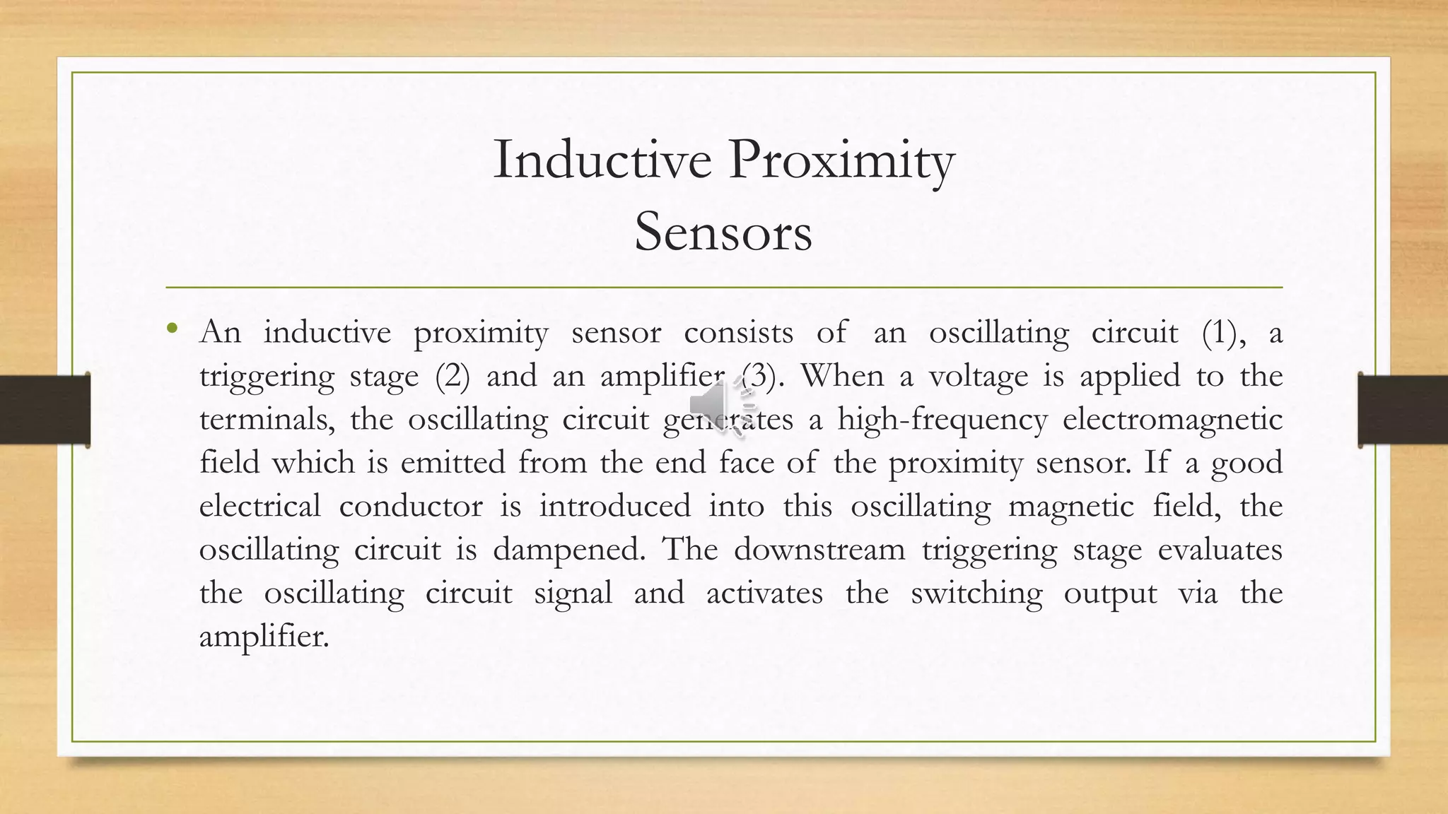
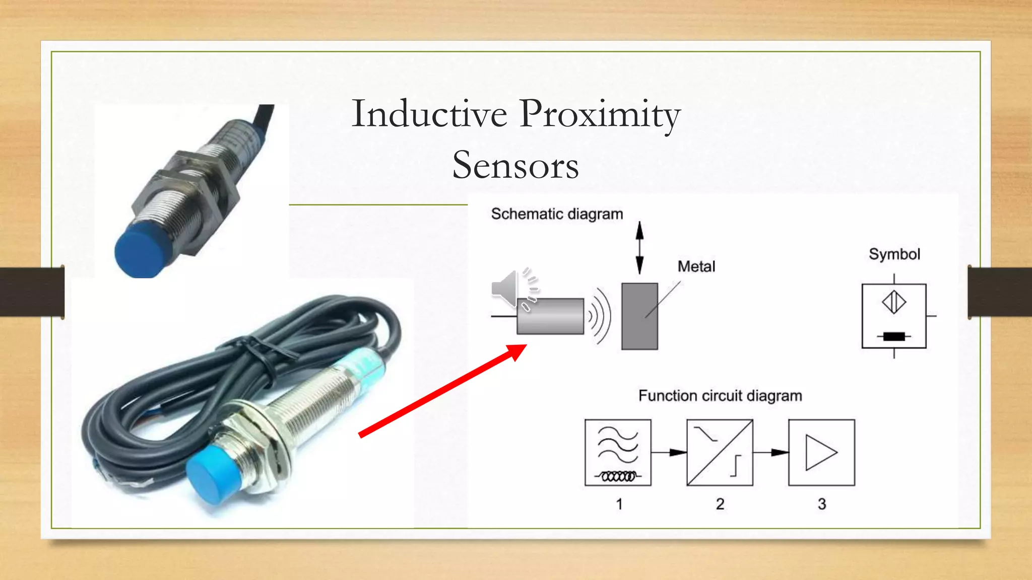
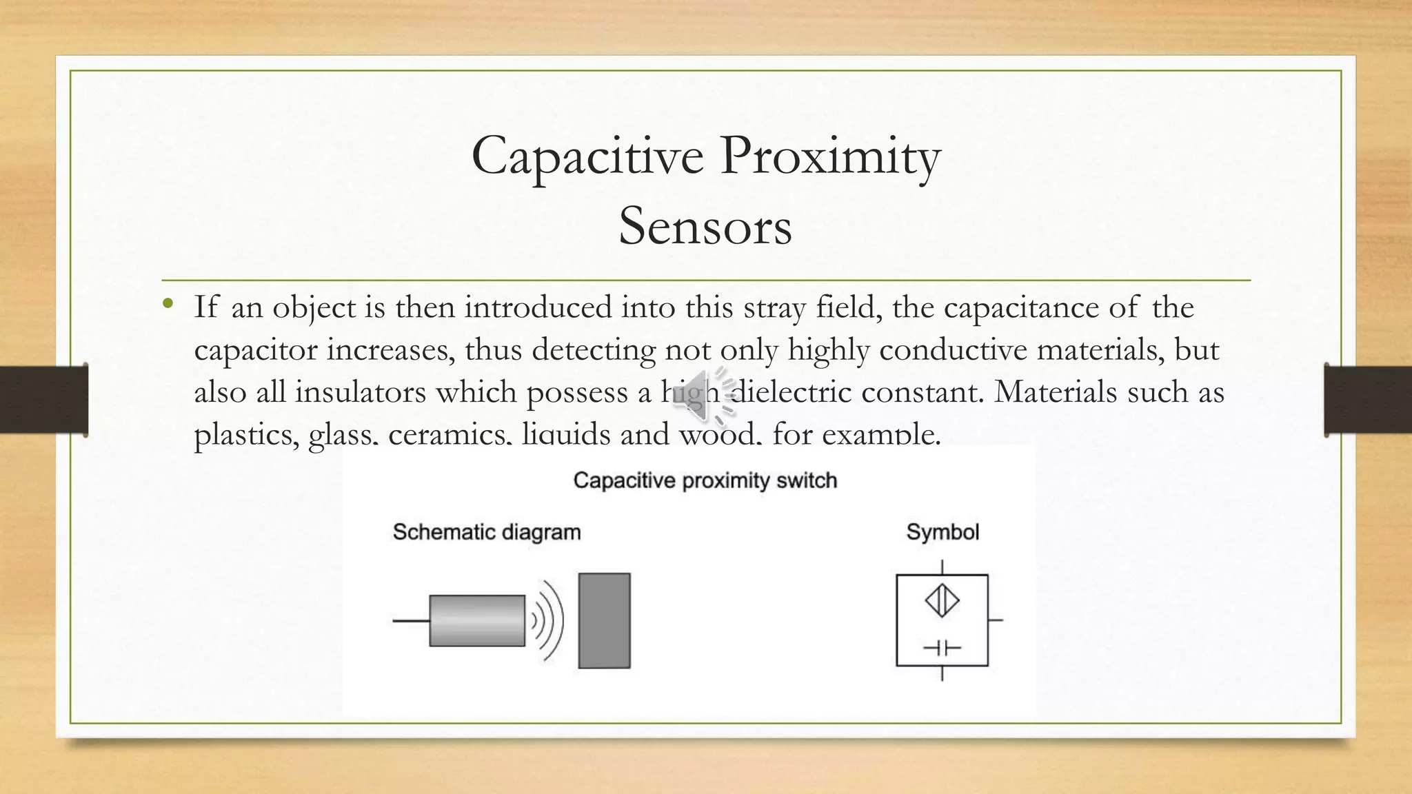
Sensor Proximity
Muhammad Akil
Pendidikan Vokasional Mekatronika
Universitas Negeri Makassar
Sensor Proximity
• Non-contacting proximity sensors differ from mechanically actuated limit switches
by virtue of the means of actuation, without external mechanical actuating force.
• A distinction is made between the following groups of proximity sensors:
1. Magnetically activated proximity sensors (Reed switch),
2. Inductive proximity sensors,
3. Capacitive proximity sensors and
4. Optical proximity sensors.
Reed switches
• Reed switches are magnetically
actuated proximity switches.
• They consist of two contact
reeds housed in a glass tube
filled with inert gas.
Symbol
Reed Switches
Reed Switches
The Working Principle of
Reed Switches
• When the switch enters a magnetic field e.g.
the magnet on a cylinder piston, the reeds are
closed and output an electrical signal. The
opening function of reed contacts can be
achieved by pre-stressing the contact reeds
using small magnets. This initial stress is
overcome by the considerably stronger
switching magnets.
Characteristics of Reed switches
• Reed switches are characterised by the following properties:
1. Long service life,
2. Maintenance-free,
3. Switching time = 0.2 ms,
4. Limited response sensitivity,
5. Unsuitable for areas with strong magnetic fields (e.g. resistance welding
machines).
Inductive Proximity
Sensors
• An inductive proximity sensor consists of an oscillating circuit (1), a
triggering stage (2) and an amplifier (3). When a voltage is applied to the
terminals, the oscillating circuit generates a high-frequency electromagnetic
field which is emitted from the end face of the proximity sensor. If a good
electrical conductor is introduced into this oscillating magnetic field, the
oscillating circuit is dampened. The downstream triggering stage evaluates
the oscillating circuit signal and activates the switching output via the
amplifier.
Inductive Proximity
Sensors
Characteristics of Inductive Proximity
Sensors
• All materials with good electrical conductivity are recognised by inductive
proximity sensors. Their function is confined toneither magnetisable
materials nor metals;
• Objects can be detected either moving or stationary.
• Objects with large surface areas are recognised more readily than objects
which are small compared to the sensor area (e.g. metal).
• They are chiefly used as digital sensors.
Capacitive Proximity
Sensors
• Capacitive proximity sensors measure the change in capacitance in the
electrical field of a capacitor caused by the approach of an object.
• The proximity sensor consists of an ohmic resistor, a capacitor (RC
oscillating circuit) and an electronic circuit.
• An electrostatic field is built up in the space between active electrode and
earth electrode.
Capacitive Proximity
Sensors
• If an object is then introduced into this stray field, the capacitance of the
capacitor increases, thus detecting not only highly conductive materials, but
also all insulators which possess a high dielectric constant. Materials such as
plastics, glass, ceramics, liquids and wood, for example.
Capacitive Proximity
Sensors
Optical Proximity
Sensors
• We distinguish between three types of optical proximity sensors:
1. Through-beam sensors
2. Retro-reflective sensors
3. Diffuse sensors
Through-Beam
Sensors
• The through-beam sensor consists
of spatially separated transmitter
and receiver units. The
components are mounted in such
a way that the transmitter is aimed
directly at the receiver. If the light
beam is interrupted, the contacts
open or close.
Through-Beam Sensors
Retro-Reflective Sensor
• In retro-reflective sensors, the transmitter
and the receiver are mounted side by side in
a common housing. For the correct
function of these sensors, a reflector must
be mounted in such a way that the light
beam emitted by the transmitter is more or
less totally reflected onto the receiver.
Interruption of the light beam causes the
sensor to switch.
Retro-Reflective Sensor
Diffuse Sensor
• The transmitter and receiver of the
diffuse sensor are mounted in a similar
way to that of the retro-reflective sensor.
If the transmitter is aimed at a reflecting
object, the reflected light is absorbed by
the receiver and a switching signal is
generated. The greater the reflection
properties of the object in question, the
more reliably the object can be detected.
Diffuse Sensor
The End Slide
•Terimakasih…….
•Selamat Belajar…….

Sensor Proximity.pptx

  • 1.
    Sensor Proximity Muhammad Akil PendidikanVokasional Mekatronika Universitas Negeri Makassar
  • 2.
    Sensor Proximity • Non-contactingproximity sensors differ from mechanically actuated limit switches by virtue of the means of actuation, without external mechanical actuating force. • A distinction is made between the following groups of proximity sensors: 1. Magnetically activated proximity sensors (Reed switch), 2. Inductive proximity sensors, 3. Capacitive proximity sensors and 4. Optical proximity sensors.
  • 3.
    Reed switches • Reedswitches are magnetically actuated proximity switches. • They consist of two contact reeds housed in a glass tube filled with inert gas. Symbol Reed Switches Reed Switches
  • 4.
    The Working Principleof Reed Switches • When the switch enters a magnetic field e.g. the magnet on a cylinder piston, the reeds are closed and output an electrical signal. The opening function of reed contacts can be achieved by pre-stressing the contact reeds using small magnets. This initial stress is overcome by the considerably stronger switching magnets.
  • 5.
    Characteristics of Reedswitches • Reed switches are characterised by the following properties: 1. Long service life, 2. Maintenance-free, 3. Switching time = 0.2 ms, 4. Limited response sensitivity, 5. Unsuitable for areas with strong magnetic fields (e.g. resistance welding machines).
  • 6.
    Inductive Proximity Sensors • Aninductive proximity sensor consists of an oscillating circuit (1), a triggering stage (2) and an amplifier (3). When a voltage is applied to the terminals, the oscillating circuit generates a high-frequency electromagnetic field which is emitted from the end face of the proximity sensor. If a good electrical conductor is introduced into this oscillating magnetic field, the oscillating circuit is dampened. The downstream triggering stage evaluates the oscillating circuit signal and activates the switching output via the amplifier.
  • 7.
  • 8.
    Characteristics of InductiveProximity Sensors • All materials with good electrical conductivity are recognised by inductive proximity sensors. Their function is confined toneither magnetisable materials nor metals; • Objects can be detected either moving or stationary. • Objects with large surface areas are recognised more readily than objects which are small compared to the sensor area (e.g. metal). • They are chiefly used as digital sensors.
  • 9.
    Capacitive Proximity Sensors • Capacitiveproximity sensors measure the change in capacitance in the electrical field of a capacitor caused by the approach of an object. • The proximity sensor consists of an ohmic resistor, a capacitor (RC oscillating circuit) and an electronic circuit. • An electrostatic field is built up in the space between active electrode and earth electrode.
  • 10.
    Capacitive Proximity Sensors • Ifan object is then introduced into this stray field, the capacitance of the capacitor increases, thus detecting not only highly conductive materials, but also all insulators which possess a high dielectric constant. Materials such as plastics, glass, ceramics, liquids and wood, for example.
  • 11.
  • 12.
    Optical Proximity Sensors • Wedistinguish between three types of optical proximity sensors: 1. Through-beam sensors 2. Retro-reflective sensors 3. Diffuse sensors
  • 13.
    Through-Beam Sensors • The through-beamsensor consists of spatially separated transmitter and receiver units. The components are mounted in such a way that the transmitter is aimed directly at the receiver. If the light beam is interrupted, the contacts open or close.
  • 14.
  • 15.
    Retro-Reflective Sensor • Inretro-reflective sensors, the transmitter and the receiver are mounted side by side in a common housing. For the correct function of these sensors, a reflector must be mounted in such a way that the light beam emitted by the transmitter is more or less totally reflected onto the receiver. Interruption of the light beam causes the sensor to switch.
  • 16.
  • 17.
    Diffuse Sensor • Thetransmitter and receiver of the diffuse sensor are mounted in a similar way to that of the retro-reflective sensor. If the transmitter is aimed at a reflecting object, the reflected light is absorbed by the receiver and a switching signal is generated. The greater the reflection properties of the object in question, the more reliably the object can be detected.
  • 18.
  • 19.