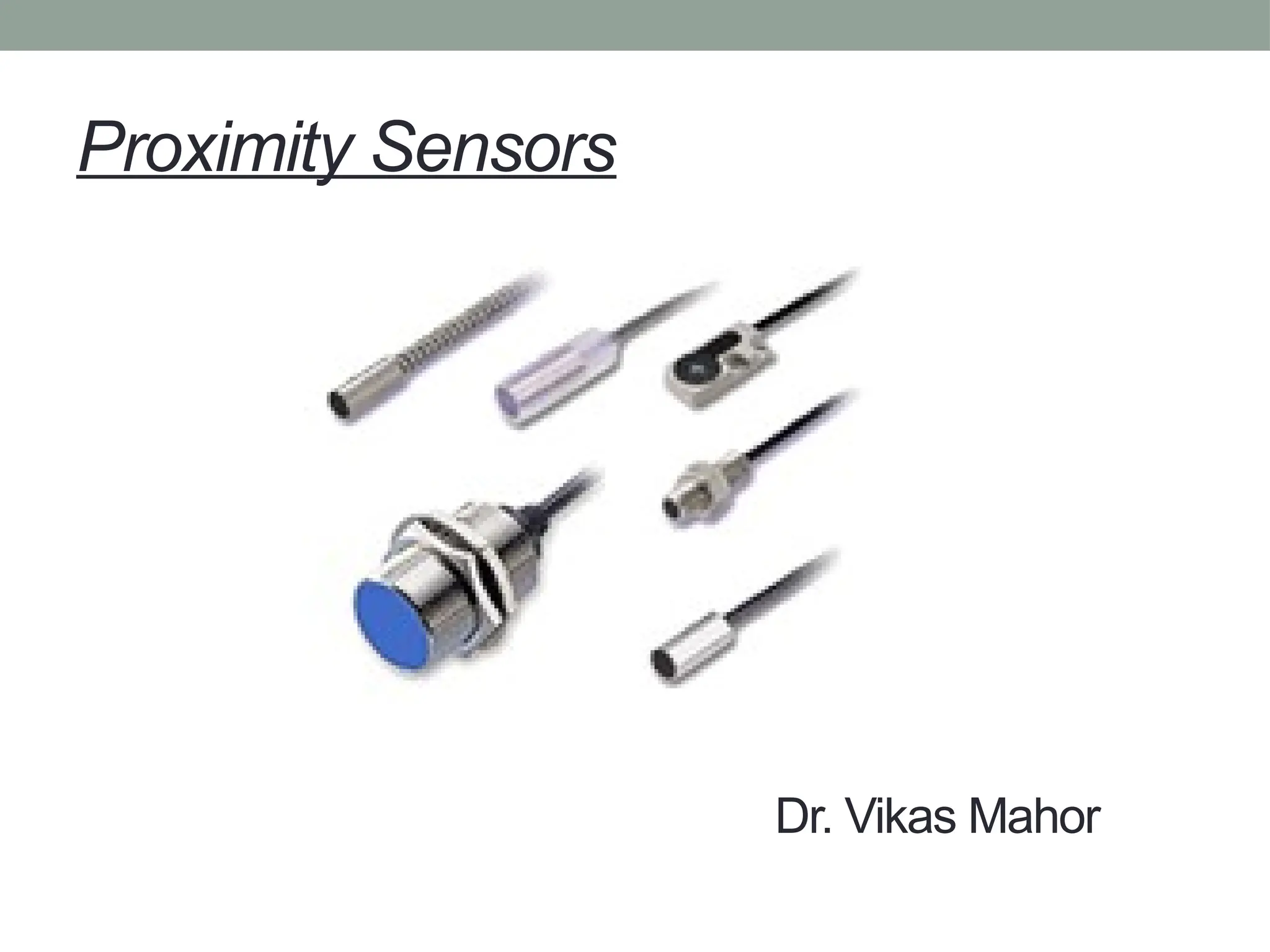
Proximity Sensors
• Proximitysensing is the technique of detecting the presence
or absence of an object with an electronic non-contact
sensor. There are four types of proximity sensors:
1. Inductive,
2. Capacitive,
3. Magnetic,
4. Photo-electric.
3.
Proximity Sensors
• Mechanicallimit switches are the first
devices to detect objects in industrial
applications.
• Inductive proximity sensors are used in place
of limit switches for non-contact sensing of
metallic objects.
• Capacitive proximity switches can also detect
non-metallic objects.
• Both inductive and capacitive sensors are limit
switches with ranges up to 100mm.
4.
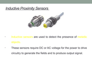
Inductive Proximity Sensors
•Inductive sensors are used to detect the presence of metallic
objects.
• These sensors require DC or AC voltage for the power to drive
circuitry to generate the fields and to produce output signal.
5.
Inductive Proximity Sensors
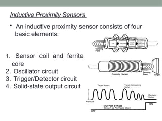
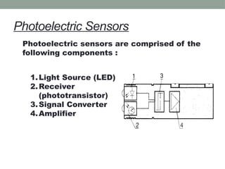
•An inductive proximity sensor consists of four
basic elements:
1. Sensor coil and ferrite
core
2. Oscillator circuit
3. Trigger/Detector circuit
4. Solid-state output circuit
6.
Inductive Proximity Sensor
workingprinciple
• The oscillator circuit generates a radio-
frequency electromagnetic field that
radiates from the ferrite core and coil
assembly.
• The field is centered around the axis of the
ferrite core, which shapes the field and
directs it at the sensor face.
• When a metal target approaches and
enters the field, eddy current are induced
into the surfaces of the target.
7.
Inductive Proximity Sensor
workingprinciple
• This results in a loading effect, or
“damping” that causes a reduction in
amplitude of the oscillator signal.
• The detector circuit detects the change in
oscillator amplitude. The detector will
switch ON at specific operate amplitude.
• This ON signal generates a signal to
turn ON the solid state output. This is
often referred to as the damped
condition.
8.
Inductive Proximity Sensor
workingprinciple
• As the target leaves the sensing field, the oscillator
responds with an increase in amplitude.
• As the amplitude increases above a specific value, it is
detected by the detector circuit, which switches OFF,
causing the output signal to return to the normal or
OFF(undamped) state.
9.
Inductive Proximity Sensor
•Typical applications of inductive proximity sensors in
control systems:
• Motion position detection
• Motion control
• Conveyor system control
• Process control
• Machine control
• Verification and counting
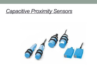
Capacitive Proximity Sensors
•Capacitive sensing is based on dielectric
capacitance.
• Capacitance is the property of insulators to store an
electric charge.
• A capacitor consists of two plates separated by an
insulator, usually called a dielectric.
• When the switch is closed a charge is stored on the
two plates.
• The distance between the plates determine the
ability of a capacitor to store a charge and can be
calibrated as a function of stored charge to
determine discrete ON and OFF switching status.
12.
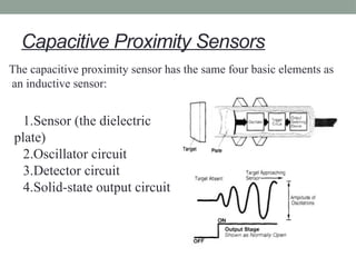
Capacitive Proximity Sensors
Thecapacitive proximity sensor has the same four basic elements as
an inductive sensor:
1.Sensor (the dielectric
plate)
2.Oscillator circuit
3.Detector circuit
4.Solid-state output circuit
13.
Capacitive Proximity Sensors
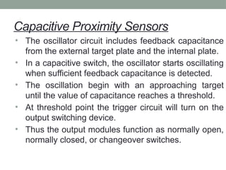
•The oscillator circuit includes feedback capacitance
from the external target plate and the internal plate.
• In a capacitive switch, the oscillator starts oscillating
when sufficient feedback capacitance is detected.
• The oscillation begin with an approaching target
until the value of capacitance reaches a threshold.
• At threshold point the trigger circuit will turn on the
output switching device.
• Thus the output modules function as normally open,
normally closed, or changeover switches.
14.
Capacitive Proximity Sensors
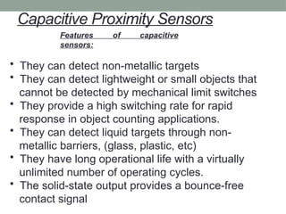
Featuresof capacitive
sensors:
• They can detect non-metallic targets
• They can detect lightweight or small objects that
cannot be detected by mechanical limit switches
• They provide a high switching rate for rapid
response in object counting applications.
• They can detect liquid targets through non-
metallic barriers, (glass, plastic, etc)
• They have long operational life with a virtually
unlimited number of operating cycles.
• The solid-state output provides a bounce-free
contact signal
15.
Capacitive Proximity Sensors
Typicalapplications of capacitive proximity sensors
in control systems:
• Liquid level detection
• Bulk material level control
• Process control
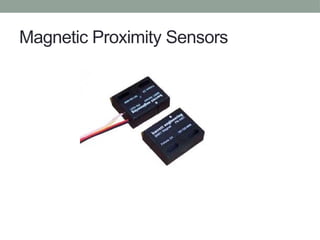
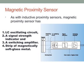
Magnetic Proximity Sensor
•As with inductive proximity sensors, magnetic
proximity sensor has
1.LC oscillating circuit,
2.A signal strength
indicator and
3.A switching amplifier.
4.Strip of magnetically
soft-glass metal.
18.
Magnetic Proximity Sensor
•This strip attenuates the oscillating circuit .
• If a magnet is brought closer, the oscillating de-attenuates.
• The power consumption of a magnetic proximity sensor
therefore increases as the magnet is brought closer
(in inductive proximity sensor the power consumption reduces
as the switching target is brought closer.)
• A major advantage of this technology is that large sensing
ranges are possible even with small sensor types.
19.
Magnetic Proximity Sensor
•Permanent magnets are usually used to trigger
magnetic proximity sensors.
Eg: magnetically hard-substances, such as steel
alloyed with other metals such as aluminum,
cobalt and nickel.
20.
Photoelectric Sensors
• Aphotoelectric sensor is a
semiconductor component that
reacts to light or emits light. The
light may be either in visible range
or the invisible infrared range.
21.
Photoelectric Sensors
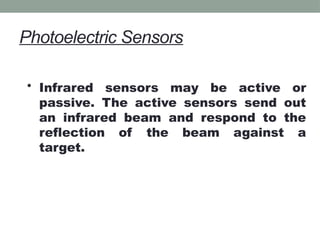
• Infraredsensors may be active or
passive. The active sensors send out
an infrared beam and respond to the
reflection of the beam against a
target.
22.
Photoelectric Sensors
• Thedistinct advantage of
photoelectric sensors over inductive
or capacitive sensors is their
increased range.
• Dirt, oil mist and other
environmental factors will hinder
operation of photoelectric sensors
during manufacturing process.
23.
Photoelectric Sensors
• Thereare three modes of detection used by
photoelectric sensors:
• Through-beam detection method
• Reflex/retro-reflective detection
method
• Proximity/Diffuse reflective
detection method
24.
Photoelectric Sensors
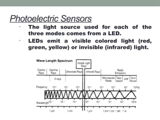
• Thelight source used for each of the
three modes comes from a LED.
• LEDs emit a visible colored light (red,
green, yellow) or invisible (infrared) light.
25.
Photoelectric Sensors
• VisibleLEDs are used for in retro-reflective
applications, they provide easy reflector
alignment to the sensor.
• Light intensity of infrared LEDs is greater than the
visible ones. They are better suited for through-
beam and diffused style sensors.
26.
Photoelectric Sensors
Switchingthe LED off and on at a
predetermined frequency (modulating),
increases the light intensity and lifetime
of the LED while reducing the average
power consumed.
• The pulsed LED provides a stronger signal
when compared to a continuously
illuminated LED, therefore, a larger
sensing range can be obtained.
27.
Photoelectric Sensors
• Anotherkey advantage to modulating the sensor
is to provide protection against external light
interference.
• The receiving circuit, typically phototransistor
based, is modulated at the same frequency as the
emitter’s.
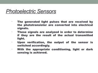
Photoelectric Sensors
• Thegenerated light pulses that are received by
the phototransistor are converted into electrical
signals.
• These signals are analyzed in order to determine
if they are the result of the actual transmitted
light.
• Upon verification, the output of the sensor is
switched accordingly.
• With the appropriate conditioning, light or dark
sensing is achieved.
30.
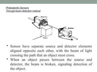
Photoelectric Sensors
Through-beam detectionmethod
• Sensor have separate source and detector elements
aligned opposite each other, with the beam of light
crossing the path that an object must cross.
• When an object passes between the source and
detector, the beam is broken, signaling detection of
the object.
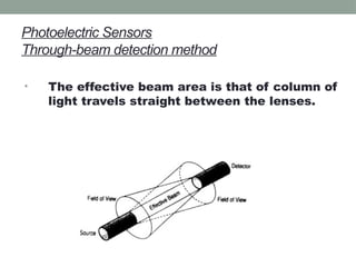
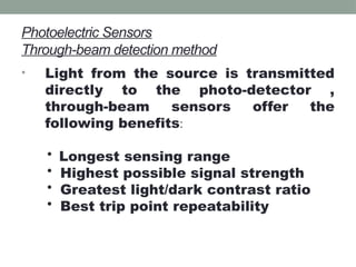
Photoelectric Sensors
Through-beam detectionmethod
• Light from the source is transmitted
directly to the photo-detector ,
through-beam sensors offer the
following benefits:
• Longest sensing range
• Highest possible signal strength
• Greatest light/dark contrast ratio
• Best trip point repeatability
33.
Photoelectric Sensors
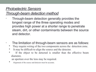
Through-beam detectionmethod
• Through-beam detection generally provides the
longest range of the three operating modes and
provides high power at a shorter range to penetrate
steam, dirt, or other contaminants between the source
and detector.
• The limitation of through-beam sensors are as follows:
• They require wiring of the two components across the detection zone.
• It may be difficult to align the source and the detector.
• If the object to be detected is smaller than the effective beam
diameter,
an aperture over the lens may be required.
• Alignment of the source and detector must be accurate.
34.
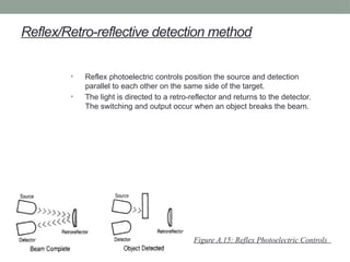
Reflex/Retro-reflective detection method
•Reflex photoelectric controls position the source and detection
parallel to each other on the same side of the target.
• The light is directed to a retro-reflector and returns to the detector.
The switching and output occur when an object breaks the beam.
Figure A.15: Reflex Photoelectric Controls
35.
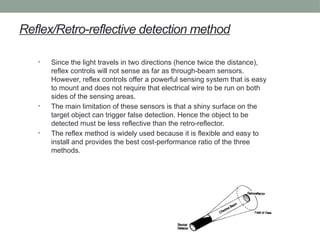
Reflex/Retro-reflective detection method
•Since the light travels in two directions (hence twice the distance),
reflex controls will not sense as far as through-beam sensors.
However, reflex controls offer a powerful sensing system that is easy
to mount and does not require that electrical wire to be run on both
sides of the sensing areas.
• The main limitation of these sensors is that a shiny surface on the
target object can trigger false detection. Hence the object to be
detected must be less reflective than the retro-reflector.
• The reflex method is widely used because it is flexible and easy to
install and provides the best cost-performance ratio of the three
methods.
36.
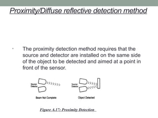
Proximity/Diffuse reflective detectionmethod
• The proximity detection method requires that the
source and detector are installed on the same side
of the object to be detected and aimed at a point in
front of the sensor.
Figure A.17: Proximity Detection
37.
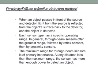
Proximity/Diffuse reflective detectionmethod
• When an object passes in front of the source
and detector, light from the source is reflected
from the object’s surface back to the detector,
and the object is detected.
• Each sensor type has a specific operating
range. In general, through-beam sensors offer
the greatest range, followed by reflex sensors,
then by proximity sensors.
• The maximum range for through-beam sensors
is of primary importance. At any distance less
than the maximum range, the sensor has more
than enough power to detect an object.
38.
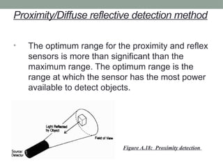
Proximity/Diffuse reflective detectionmethod
• The optimum range for the proximity and reflex
sensors is more than significant than the
maximum range. The optimum range is the
range at which the sensor has the most power
available to detect objects.
Figure A.18: Proximity detection
39.
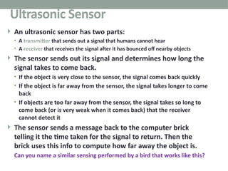
An ultrasonicsensor has two parts:
• A transmitter that sends out a signal that humans cannot hear
• A receiver that receives the signal after it has bounced off nearby objects
The sensor sends out its signal and determines how long the
signal takes to come back.
• If the object is very close to the sensor, the signal comes back quickly
• If the object is far away from the sensor, the signal takes longer to come
back
• If objects are too far away from the sensor, the signal takes so long to
come back (or is very weak when it comes back) that the receiver
cannot detect it
The sensor sends a message back to the computer brick
telling it the time taken for the signal to return. Then the
brick uses this info to compute how far away the object is.
Can you name a similar sensing performed by a bird that works like this?
39
Ultrasonic Sensor
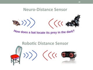
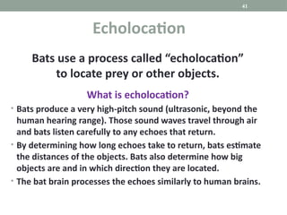
Bats use aprocess called “echolocation”
to locate prey or other objects.
What is echolocation?
• Bats produce a very high-pitch sound (ultrasonic, beyond the
human hearing range). Those sound waves travel through air
and bats listen carefully to any echoes that return.
• By determining how long echoes take to return, bats estimate
the distances of the objects. Bats also determine how big
objects are and in which direction they are located.
• The bat brain processes the echoes similarly to human brains.
41
Echolocation
42.
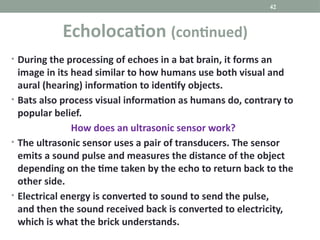
• During theprocessing of echoes in a bat brain, it forms an
image in its head similar to how humans use both visual and
aural (hearing) information to identify objects.
• Bats also process visual information as humans do, contrary to
popular belief.
How does an ultrasonic sensor work?
• The ultrasonic sensor uses a pair of transducers. The sensor
emits a sound pulse and measures the distance of the object
depending on the time taken by the echo to return back to the
other side.
• Electrical energy is converted to sound to send the pulse,
and then the sound received back is converted to electricity,
which is what the brick understands.
42
Echolocation (continued)
43.
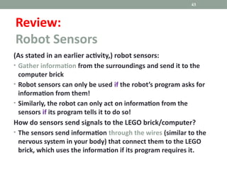
(As stated inan earlier activity,) robot sensors:
• Gather information from the surroundings and send it to the
computer brick
• Robot sensors can only be used if the robot’s program asks for
information from them!
• Similarly, the robot can only act on information from the
sensors if its program tells it to do so!
How do sensors send signals to the LEGO brick/computer?
• The sensors send information through the wires (similar to the
nervous system in your body) that connect them to the LEGO
brick, which uses the information if its program requires it.
43
Review:
Robot Sensors
44.
44
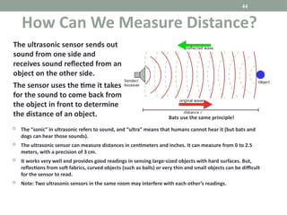
The “sonic”in ultrasonic refers to sound, and “ultra” means that humans cannot hear it (but bats and
dogs can hear those sounds).
The ultrasonic sensor can measure distances in centimeters and inches. It can measure from 0 to 2.5
meters, with a precision of 3 cm.
It works very well and provides good readings in sensing large-sized objects with hard surfaces. But,
reflections from soft fabrics, curved objects (such as balls) or very thin and small objects can be difficult
for the sensor to read.
Note: Two ultrasonic sensors in the same room may interfere with each other’s readings.
How Can We Measure Distance?
The ultrasonic sensor sends out
sound from one side and
receives sound reflected from an
object on the other side.
The sensor uses the time it takes
for the sound to come back from
the object in front to determine
the distance of an object. Bats use the same principle!
45.
45
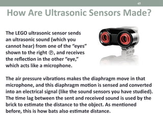
The LEGO ultrasonicsensor sends
an ultrasonic sound (which you
cannot hear) from one of the “eyes”
shown to the right , and receives
the reflection in the other “eye,”
which acts like a microphone.
The air pressure vibrations makes the diaphragm move in that
microphone, and this diaphragm motion is sensed and converted
into an electrical signal (like the sound sensors you have studied).
The time lag between the sent and received sound is used by the
brick to estimate the distance to the object. As mentioned
before, this is how bats also estimate distance.
How Are Ultrasonic Sensors Made?
Editor's Notes
#39 Bats, dolphins, porpoises and some whales use echolocation, sometimes called biosonar.


![PHOTO ELECTRIC SENSORS [Autosaved].pptx](https://cdn.slidesharecdn.com/ss_thumbnails/photoelectricsensorsautosaved-230122195642-139c3524-thumbnail.jpg?width=640&height=640&fit=bounds)


