Download to read offline


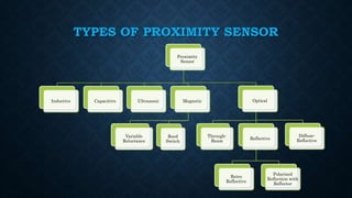


The document provides an overview of various types of proximity sensors, which detect objects without contact using different methods such as sound, electromagnetic waves, and optical techniques. It details the principles and components of inductive, capacitive, ultrasonic, magnetic, and optical sensors, highlighting their applications and operation mechanisms. Each sensor type has unique functionalities suited for different industrial uses and environmental conditions.


