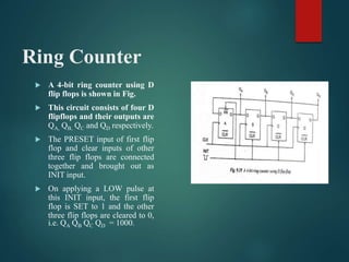
Ring Counter
III PHYSICS – 08.04.2022
DR.R.HEPZI PRAMILA DEVAMANI,
ASSISTANT PROFESSOR OF PHYSICS,
V.V.VANNIAPERUMAL COLLEGE FOR WOMEN,
VIRUDHUNAGAR.
Ring Counter
 In a ring counter, the true output Q of the last flip flop in a
shift register is connected back to the serial input of the first
flip flop and also only one flip flop is set at any particular
time while all others are cleared.
 The flip flops are connected in such a way that information
shifts either from left to right and back around from QD to
QA or from right to left and back around from QA to QD.
 Since a single 1 in the register is made to circulate around th
register as long as clock pulses are applied, it is called a ring
counter.
Ring Counter
 A 4-bit ring counter using D
flip flops is shown in Fig.
 This circuit consists of four D
flipflops and their outputs are
QA, QB, QC and QD respectively.
 The PRESET input of first flip
flop and clear inputs of other
three flip flops are connected
together and brought out as
INIT input.
 On applying a LOW pulse at
this INIT input, the first flip
flop is SET to 1 and the other
three flip flops are cleared to 0,
i.e. QA QB QC QD = 1000.
Ring Counter
 From this circuit it is clear that DA = 0, DB= 0, DC= 0, and DD = 0.
 When the clock pulse is applied, the second flip flop is set to 1 while the other
three flip flops are reset to zero. i.e. the output of the ring counter is QA QB QC
QD = 0100.
 On the occurrence of the first clock pulse, the 1 in the first flip flop is shifted
to the second flip flop.
 Similarly, when the second clock pulse is applied, the 1 in the second flip flop
is shifted to the third flip flop and the ring counter output QA QB QC QD =
0010.
 On the occurrence of the fourth clock pulse, the output will be QA QB QC QD =
0001.
Ring Counter
 On the fifth clock pulse QA
QB QC QD = 1000, i.e. the
initial state.
 Thus, 1 is shifted or
circulated around the
register as long as clock
pulses are applied.
 The truth table which
describes the operation of
4- bit ring counter s
shown.
Ring Counter
 As in the truth table, the ring counter has only 4
valid states i.e. 1000, 0100,0010,0001.
 The ring counter can hang or enter into any one of
the invalid state due to noise or any other
condition without returning to the main counting
sequence.
 Hence it is a must to design ring counters which
are self correcting and capable of recovering from
invalid states to valid states.
THANK YOU

Ring Counter.pptx

  • 1.
    Ring Counter III PHYSICS– 08.04.2022 DR.R.HEPZI PRAMILA DEVAMANI, ASSISTANT PROFESSOR OF PHYSICS, V.V.VANNIAPERUMAL COLLEGE FOR WOMEN, VIRUDHUNAGAR.
  • 2.
    Ring Counter  Ina ring counter, the true output Q of the last flip flop in a shift register is connected back to the serial input of the first flip flop and also only one flip flop is set at any particular time while all others are cleared.  The flip flops are connected in such a way that information shifts either from left to right and back around from QD to QA or from right to left and back around from QA to QD.  Since a single 1 in the register is made to circulate around th register as long as clock pulses are applied, it is called a ring counter.
  • 3.
    Ring Counter  A4-bit ring counter using D flip flops is shown in Fig.  This circuit consists of four D flipflops and their outputs are QA, QB, QC and QD respectively.  The PRESET input of first flip flop and clear inputs of other three flip flops are connected together and brought out as INIT input.  On applying a LOW pulse at this INIT input, the first flip flop is SET to 1 and the other three flip flops are cleared to 0, i.e. QA QB QC QD = 1000.
  • 4.
    Ring Counter  Fromthis circuit it is clear that DA = 0, DB= 0, DC= 0, and DD = 0.  When the clock pulse is applied, the second flip flop is set to 1 while the other three flip flops are reset to zero. i.e. the output of the ring counter is QA QB QC QD = 0100.  On the occurrence of the first clock pulse, the 1 in the first flip flop is shifted to the second flip flop.  Similarly, when the second clock pulse is applied, the 1 in the second flip flop is shifted to the third flip flop and the ring counter output QA QB QC QD = 0010.  On the occurrence of the fourth clock pulse, the output will be QA QB QC QD = 0001.
  • 5.
    Ring Counter  Onthe fifth clock pulse QA QB QC QD = 1000, i.e. the initial state.  Thus, 1 is shifted or circulated around the register as long as clock pulses are applied.  The truth table which describes the operation of 4- bit ring counter s shown.
  • 6.
    Ring Counter  Asin the truth table, the ring counter has only 4 valid states i.e. 1000, 0100,0010,0001.  The ring counter can hang or enter into any one of the invalid state due to noise or any other condition without returning to the main counting sequence.  Hence it is a must to design ring counters which are self correcting and capable of recovering from invalid states to valid states.
  • 7.