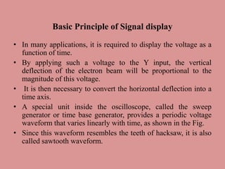
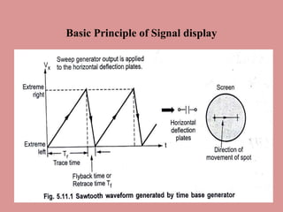
Basic Principle of Signal display
II PHYSICS – 06.02.2023
Dr.R.Hepzi Pramila Devamani,
Assistant Professor of Physics,
V.V.Vanniaperumal College for Women,
Virudhunagar.
Basic Principle of Signal display
• In many applications, it is required to display the voltage as a
function of time.
• By applying such a voltage to the Y input, the vertical
deflection of the electron beam will be proportional to the
magnitude of this voltage.
• It is then necessary to convert the horizontal deflection into a
time axis.
• A special unit inside the oscilloscope, called the sweep
generator or time base generator, provides a periodic voltage
waveform that varies linearly with time, as shown in the Fig.
• Since this waveform resembles the teeth of hacksaw, it is also
called sawtooth waveform.
Basic Principle of Signal display
• Assume that no voltage is applied to vertical deflecting plates, but only
this sawtooth voltage V, is applied to the horizontal deflecting plates.
• During the trace time T, the voltage V, is linearly increasing with time,
and hence the electron beam will move linearly in the horizontal direction.
• At the end of trace period T, the beam reaches extreme right hand position
in the horizontal direction.
• At this, instant, the voltage suddenly drops to zero in a short interval of
time, known as flyback period.
• Hence the beam jumps back to the original positions at the extreme left
hand side.
• Then again it starts moving to the right during the next cycle of sawtooth
waveform. The fly back of the beam is blanked out by a suitable voltage
and is not visible on the screen.
Basic Principle of Signal display
• Thus for a selected trace time T, the spot moves horizontally
across the face of the screen along the x-axis from left to
right, with a constant speed, restarts again from the left, and
repeats such traces.
• Depending on the speed of the bright spot and the persistence
of vision, the trace produced by the spot will look like a
horizontal straight line. Thus the horizontal axis is now
converted into a time axis.
Basic Principle of Signal display
• When a periodically varying voltage say sinusoidal
voltage is applied to the y terminal of the scope and
internally generated sawtooth voltage is applied to the
horizontal deflection plates, then sawtooth voltage
keeps on shifting the spot horizontally while the
applied voltage shifts the spot vertically proportional
to its magnitude.
• Hence finally due to the effect of both the voltage, a
familiar sinusoidal waveform can be observed on the
screen.
Basic Principle of Signal display
• When the sweep and signal frequencies are equal, a
single cycle appears on the screen.
• When the sweep is lower than the signal, several
cycles appear on the screen.
• In such case, the number of cycles depends on the
ratio of the two frequencies.
• When the sweep is higher than the signal, less than
one cycle appears on the screen.
Basic Principle of Signal display
• The display of spot on the screen appears stationary only when the
two frequencies i.e. sweep and signal are same or are integral
multiples of each other.
• For any other frequencies the trace on the screen keeps on drifting
horizontally.
• Thus for the trace to appear stationary, the sawtooth voltage is
synchronized with signal applied to the vertical input.
• For the vertical input signal, the triggering pulses are derived for the
synchronization.
• There are two important requirements of a sweep generator, The
sweep must be linear in nature, for all screen horizontal deflection.
• To move the spot in one direction only, the sweep voltage must drop
to zero suddenly, after reaching its maximum value.
• Otherwise the return sweep will trace the signal backwards.
THANK YOU

Basic Principle of signal display.pptx

  • 1.
    Basic Principle ofSignal display II PHYSICS – 06.02.2023 Dr.R.Hepzi Pramila Devamani, Assistant Professor of Physics, V.V.Vanniaperumal College for Women, Virudhunagar.
  • 2.
    Basic Principle ofSignal display • In many applications, it is required to display the voltage as a function of time. • By applying such a voltage to the Y input, the vertical deflection of the electron beam will be proportional to the magnitude of this voltage. • It is then necessary to convert the horizontal deflection into a time axis. • A special unit inside the oscilloscope, called the sweep generator or time base generator, provides a periodic voltage waveform that varies linearly with time, as shown in the Fig. • Since this waveform resembles the teeth of hacksaw, it is also called sawtooth waveform.
  • 3.
    Basic Principle ofSignal display
  • 4.
    Basic Principle ofSignal display • Assume that no voltage is applied to vertical deflecting plates, but only this sawtooth voltage V, is applied to the horizontal deflecting plates. • During the trace time T, the voltage V, is linearly increasing with time, and hence the electron beam will move linearly in the horizontal direction. • At the end of trace period T, the beam reaches extreme right hand position in the horizontal direction. • At this, instant, the voltage suddenly drops to zero in a short interval of time, known as flyback period. • Hence the beam jumps back to the original positions at the extreme left hand side. • Then again it starts moving to the right during the next cycle of sawtooth waveform. The fly back of the beam is blanked out by a suitable voltage and is not visible on the screen.
  • 5.
    Basic Principle ofSignal display • Thus for a selected trace time T, the spot moves horizontally across the face of the screen along the x-axis from left to right, with a constant speed, restarts again from the left, and repeats such traces. • Depending on the speed of the bright spot and the persistence of vision, the trace produced by the spot will look like a horizontal straight line. Thus the horizontal axis is now converted into a time axis.
  • 6.
    Basic Principle ofSignal display • When a periodically varying voltage say sinusoidal voltage is applied to the y terminal of the scope and internally generated sawtooth voltage is applied to the horizontal deflection plates, then sawtooth voltage keeps on shifting the spot horizontally while the applied voltage shifts the spot vertically proportional to its magnitude. • Hence finally due to the effect of both the voltage, a familiar sinusoidal waveform can be observed on the screen.
  • 7.
    Basic Principle ofSignal display • When the sweep and signal frequencies are equal, a single cycle appears on the screen. • When the sweep is lower than the signal, several cycles appear on the screen. • In such case, the number of cycles depends on the ratio of the two frequencies. • When the sweep is higher than the signal, less than one cycle appears on the screen.
  • 8.
    Basic Principle ofSignal display • The display of spot on the screen appears stationary only when the two frequencies i.e. sweep and signal are same or are integral multiples of each other. • For any other frequencies the trace on the screen keeps on drifting horizontally. • Thus for the trace to appear stationary, the sawtooth voltage is synchronized with signal applied to the vertical input. • For the vertical input signal, the triggering pulses are derived for the synchronization. • There are two important requirements of a sweep generator, The sweep must be linear in nature, for all screen horizontal deflection. • To move the spot in one direction only, the sweep voltage must drop to zero suddenly, after reaching its maximum value. • Otherwise the return sweep will trace the signal backwards.
  • 9.