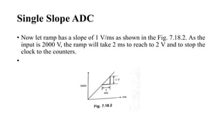
Single Slope ADC
Dr.R.Hepzi Pramila Devamani,
Assistant Professor of Physics,
V.V.Vanniaperumal College for Women,
Virudhunagar.
Analog to Digital Conversion Techniques
• Analog to digital converters are classified into two general groups
based on the conversion techniques.
• One technique involves comparing a given analog signal with the
internally generated reference voltages.
• This group includes successive approximation, flash, delta modulated
(DM), adaptive delta modulated and flash type converters.
• The another technique involves changing an analog signal into time or
frequency and comparing these new parameters against known values.
• This group includes integrator converters and voltage-to-frequency
converters.
Types of ADC
• Single ramp or single slope ADC
• Dual slope ADC
• Successive approximation ADC
• Flash ADC
• Delta modulation ADC
• Adaptive delta modulation ADC
Single Slope ADC
• It consists of a ramp generator and BCD or binary counters.
Single Slope ADC
• At the start, the reset signal is provided to the ramp generator and the
counters.
• Thus counters are resetted to 0's. The analog input voltage V is applied
to the positive terminal of the comparator.
• As this is more positive than the negative input, the comparator output
goes high.
• The output of ramp generator is applied to the negative terminal of the
comparator.
• The high output of the comparator enables the AND gate which allows
clock to reach to the counters and also this high output starts the ramp.
Single Slope ADC
• The ramp voltage goes positive until it exceeds the input voltage.
• When it exceeds Vin comparator output goes low. This disables AND gate
which inturn stops the clock to the counters.
• The control circuitry provides the latch signal which is used to latch the
counter data.
• The reset signal resets the counters to O's and also resets the ramp generator.
• The latched data is then displayed using decoder and a display device.
Consider the practical example to understand the working.
• Assume that the clock frequency is 1 MHz There are four BCD counters
and the input Vin 2.000 V.
Single Slope ADC
• Now let ramp has a slope of 1 V/ms as shown in the Fig. 7.18.2. As the
input is 2000 V, the ramp will take 2 ms to reach to 2 V and to stop the
clock to the counters.
•
Single Slope ADC
• Now how many pulses will reach to the counters during 2 ms ? It can
be calculated from the frequency of the clock.
• The number of pulses reaching to the counter in 2 ms is 2ms/(1/1
MHz) = 2000. The comparator output going high will strobe.
• The latches and send the count to the displays. Inserting decimal point
at the proper point in the seven segment display gives a reading of
2000 But we want binary output.
• In such case instead of BCD counters, binary counters must be used,
where output will be straight binary coded.
Single Slope ADC
The main limitations of this circuit are,
• i) Its resolution is less. Hence for applications which require resolution
of 9 part in 20,000 or more, this ADC is not stable.
• ii) Variations in ramp generator due to time, temperature or input
voltage sensitivity also cause a lot of problems.
THANK YOU

Single Slope ADC.pptx

  • 1.
    Single Slope ADC Dr.R.HepziPramila Devamani, Assistant Professor of Physics, V.V.Vanniaperumal College for Women, Virudhunagar.
  • 2.
    Analog to DigitalConversion Techniques • Analog to digital converters are classified into two general groups based on the conversion techniques. • One technique involves comparing a given analog signal with the internally generated reference voltages. • This group includes successive approximation, flash, delta modulated (DM), adaptive delta modulated and flash type converters. • The another technique involves changing an analog signal into time or frequency and comparing these new parameters against known values. • This group includes integrator converters and voltage-to-frequency converters.
  • 3.
    Types of ADC •Single ramp or single slope ADC • Dual slope ADC • Successive approximation ADC • Flash ADC • Delta modulation ADC • Adaptive delta modulation ADC
  • 4.
    Single Slope ADC •It consists of a ramp generator and BCD or binary counters.
  • 5.
    Single Slope ADC •At the start, the reset signal is provided to the ramp generator and the counters. • Thus counters are resetted to 0's. The analog input voltage V is applied to the positive terminal of the comparator. • As this is more positive than the negative input, the comparator output goes high. • The output of ramp generator is applied to the negative terminal of the comparator. • The high output of the comparator enables the AND gate which allows clock to reach to the counters and also this high output starts the ramp.
  • 6.
    Single Slope ADC •The ramp voltage goes positive until it exceeds the input voltage. • When it exceeds Vin comparator output goes low. This disables AND gate which inturn stops the clock to the counters. • The control circuitry provides the latch signal which is used to latch the counter data. • The reset signal resets the counters to O's and also resets the ramp generator. • The latched data is then displayed using decoder and a display device. Consider the practical example to understand the working. • Assume that the clock frequency is 1 MHz There are four BCD counters and the input Vin 2.000 V.
  • 7.
    Single Slope ADC •Now let ramp has a slope of 1 V/ms as shown in the Fig. 7.18.2. As the input is 2000 V, the ramp will take 2 ms to reach to 2 V and to stop the clock to the counters. •
  • 8.
    Single Slope ADC •Now how many pulses will reach to the counters during 2 ms ? It can be calculated from the frequency of the clock. • The number of pulses reaching to the counter in 2 ms is 2ms/(1/1 MHz) = 2000. The comparator output going high will strobe. • The latches and send the count to the displays. Inserting decimal point at the proper point in the seven segment display gives a reading of 2000 But we want binary output. • In such case instead of BCD counters, binary counters must be used, where output will be straight binary coded.
  • 9.
    Single Slope ADC Themain limitations of this circuit are, • i) Its resolution is less. Hence for applications which require resolution of 9 part in 20,000 or more, this ADC is not stable. • ii) Variations in ramp generator due to time, temperature or input voltage sensitivity also cause a lot of problems.
  • 10.