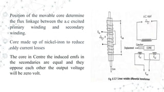
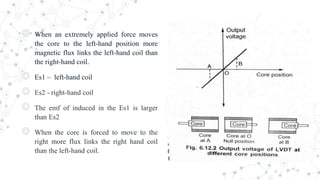
CONSTRUCTION AND WORKING OF LVDT
◎ LVDT - LINEAR VARIABLE DIFFERENTIAL
TRANSDUCER
◎ The linear variable differential transducer consists of
◎ P1 – One Primary winding.
◎ S1 and S2- Two Secondary winding on Hollow cylindrical former.
◎ The secondaries have an equal number of turns connected in series.
◎ The emf induced in the coil oppose each other.
◎ The Primary winding connected to an AC source.
◎ Frequency range 50Hz to 20kHz.
◎ Position of the movable core determine
the flux linkage between the a.c excited
primary winding and secondary
winding.
◎ Core made up of nickel-iron to reduce
eddy current losses
◎ The core in Centre the induced emfs in
the secondaries are equal and they
oppose each other the output voltage
will be zero volt.
◎ When an extremely applied force moves
the core to the left-hand position more
magnetic flux links the left-hand coil than
the right-hand coil.
◎ Es1 – left-hand coil
◎ Es2 - right-hand coil
◎ The emf of induced in the Es1 is larger
than Es2
◎ When the core is forced to move to the
right more flux links the right hand coil
than the left-hand coil.
◎ LVDT output voltage is a function of the core position.
◎ The amount of a voltage change in either secondary winding is proportional
to the amount of movement of the core.
◎ By noting which output is increasing or decreasing the direction is
determined.
◎ The core moves from the Centre the greater difference in value between Es1
and Es2and consequently greater the output.
◎ The amount of output voltage of an LVDT is an linear function of the core
display within a limited range of motion.
THANK YOU

LINEAR VARIABLE DIFFERENTIAL TRANSDUCER.pptx

  • 1.
  • 2.
    ◎ LVDT -LINEAR VARIABLE DIFFERENTIAL TRANSDUCER ◎ The linear variable differential transducer consists of ◎ P1 – One Primary winding. ◎ S1 and S2- Two Secondary winding on Hollow cylindrical former. ◎ The secondaries have an equal number of turns connected in series. ◎ The emf induced in the coil oppose each other. ◎ The Primary winding connected to an AC source. ◎ Frequency range 50Hz to 20kHz.
  • 3.
    ◎ Position ofthe movable core determine the flux linkage between the a.c excited primary winding and secondary winding. ◎ Core made up of nickel-iron to reduce eddy current losses ◎ The core in Centre the induced emfs in the secondaries are equal and they oppose each other the output voltage will be zero volt.
  • 4.
    ◎ When anextremely applied force moves the core to the left-hand position more magnetic flux links the left-hand coil than the right-hand coil. ◎ Es1 – left-hand coil ◎ Es2 - right-hand coil ◎ The emf of induced in the Es1 is larger than Es2 ◎ When the core is forced to move to the right more flux links the right hand coil than the left-hand coil.
  • 5.
    ◎ LVDT outputvoltage is a function of the core position. ◎ The amount of a voltage change in either secondary winding is proportional to the amount of movement of the core. ◎ By noting which output is increasing or decreasing the direction is determined. ◎ The core moves from the Centre the greater difference in value between Es1 and Es2and consequently greater the output. ◎ The amount of output voltage of an LVDT is an linear function of the core display within a limited range of motion.
  • 6.