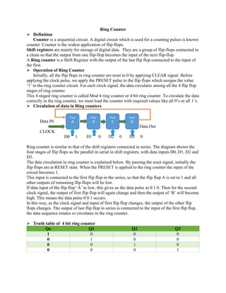
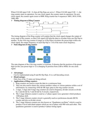
Call Girls In Vaishali 📱 9999965857 🤩 Delhi 🫦 HOT AND SEXY VVIP 🍎 SERVICE
Ring counter
1. Ring Counter
➢ Definition
Counter is a sequential circuit. A digital circuit which is used for a counting pulses is known
counter. Counter is the widest application of flip-flops.
Shift registers are mainly for storage of digital data. They are a group of flip-flops connected in
a chain so that the output from one flip-flop becomes the input of the next flip-flop.
A Ring counter is a Shift Register with the output of the last flip flop connected to the input of
the first.
➢ Operation of Ring Counter
Initially, all the flip flops in ring counter are reset to 0 by applying CLEAR signal. Before
applying the clock pulse, we apply the PRESET pulse to the flip flops which assigns the value
‘1’ to the ring counter circuit. For each clock signal, the data circulates among all the 4 flip flop
stages of ring counter.
This 4 staged ring counter is called Mod 4 ring counter or 4 bit ring counter. To circulate the data
correctly in the ring counter, we must load the counter with required values like all 0’s or all 1’s.
➢ Circulation of data in Ring counters
Data IN
Data Out
CLOCK
D0 1 D1 0 D2 0 D3 0
Ring counter is similar to that of the shift registers connected in series. The diagram shown the
four stages of flip flops as the parallel in serial in shift registers, with data inputs D0, D1, D2 and
D3.
The data circulation in ring counter is explained below. By passing the reset signal, initially the
flip flops are at RESET state. When the PRESET is applied to the ring counter the input of the
circuit becomes 1.
This input is connected to the first flip flop in the series, so that the flip flop A is set to 1 and all
other outputs of remaining flip flops will be low.
If data input of the flip flop ‘A’ to low, this gives us the data pulse as 0 1 0. Then for the second
clock signal, the output of first flip flop will again change and then the output of ‘B’ will become
high. This means the data pulse 0 0 1 occurs.
In this way, as the clock signal and input of first flip flop changes, the output of the other flip
flops changes. The output of last flip flop in series is connected to the input of the first flip flop,
the data sequence rotates or circulates in the ring counter.
➢ Truth table of 4 bit ring counter
Qo Q1 Q2 Q3
1 0 0 0
0 1 0 0
0 0 1 0
0 0 0 1
Stage
A
Stage
B
Stage
C
Stage
D
F
F
F
F
2. When CLEAR input CLR = 0, then all flip flops are set to 1. When CLEAR input CLR = 1, the
ring counter starts its operation. For one clock signal, the counter starts its operation. On next
clock signal, the counter again resets to 0000. Ring counter has 4 sequences: 0001, 0010, 0100,
1000, 000.
➢ Timing diagram of Ring Counter
The timing diagram of the Ring counter will explain that the clock signal changes the output of
every stage of the counter, so that CLK signal will help the data to circulate from one flip flop to
another. As the 4 bit ring counter (4 stages or 4 flip flops) circulates the preset digit within one
clock signal, the output frequency of each flip flop is ¼ th of the main clock frequency.
➢ State diagram of ring counter
The state diagram of the 4 bit ring counter is in picture. It denotes that the position of the preset
digit (in this case preset digit is 1) is changing its position from LSB to MSB, for one clock
signal.
➢ Advantages
Can be implemented using D and JK flip-flops. It is a self-decoding circuit.
➢ Disadvantages
Only four of the 15 states are being utilized.
➢ Applications of Ring counters
1. Ring counters are used to count the data in a continuous loop.
2. They are also used to detect the various numbers values or various patterns within a set of
information, by connecting AND & OR logic gates to the ring counter circuits.
3. 2 stage, 3 stage and 4 stage ring counters are used in frequency divider circuits as divide
by 2 and divide by 3 and divide by 4 circuits, respectively.
4. The 3 stage Johnson counter is used as a 3 phase square wave generator which produces
1200 phase shift.
5. The 5 stage Johnson counter circuit is generally used as synchronous decade (BCD)
counter and also as divider circuit.
6. The 2 stage Johnson counters are also known as “Quadrature oscillator” which is used to
produce 4 level individual outputs which are out of phase with 900 with each other. This
quadrature generator is used to produce 4 phase timing signal.
S0
0001
S1
0010
S2
1000
S3
0100
Fsaf
F