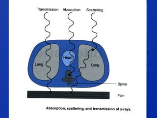
X-rays can interact with matter in three ways:
1. They can be absorbed, where all the X-ray's energy is transferred into the patient's tissue.
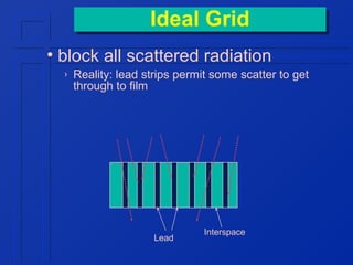
2. They can be scattered, where the X-ray changes direction and loses some energy.
3. They can be transmitted through the patient without interaction. Most diagnostic X-rays are either absorbed or scattered within the patient.