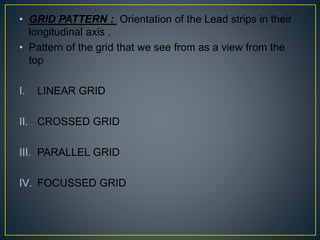
Downloaded 2,025 times
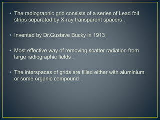
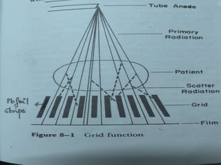
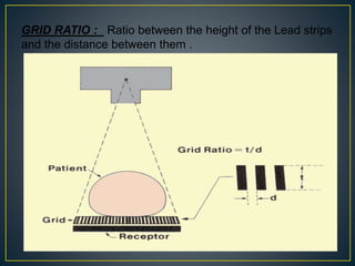
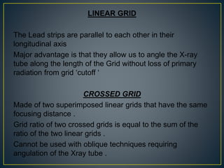
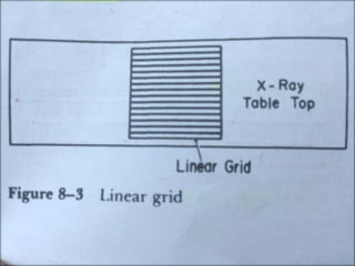
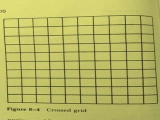
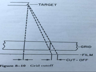
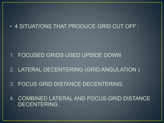
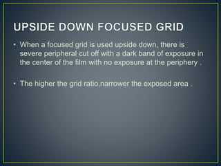
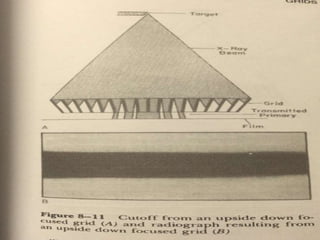
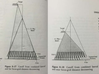
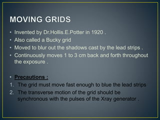
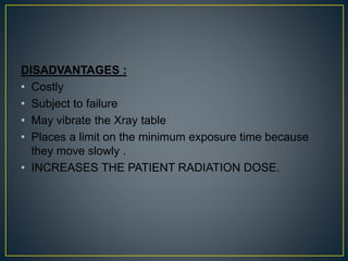
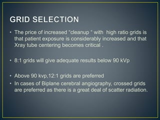
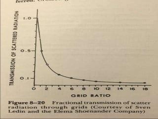
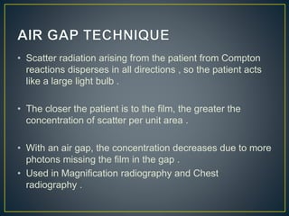
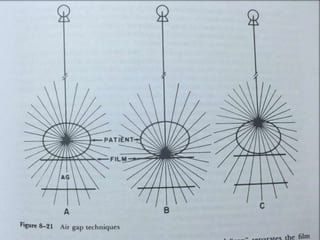
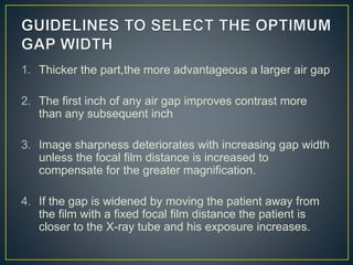


The document summarizes key aspects of radiographic grids used to reduce scatter radiation in x-ray imaging. It describes the components and invention of grids, different grid patterns like linear and focused grids, as well as factors that affect grid performance such as grid ratio and lines per inch. Methods for evaluating grids like primary transmission, Bucky factor and contrast improvement are also outlined. Potential issues with grid use involving cutoff and decentering are discussed.


![Hypothalamus short notes on location, function and disorders by Dr. Neha [PT]...](https://cdn.slidesharecdn.com/ss_thumbnails/hypothalamusbydr-260124142231-2b48143d-thumbnail.jpg?width=640&height=640&fit=bounds)


