Downloaded 1,013 times

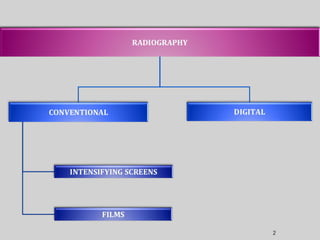
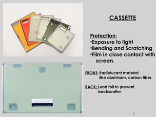
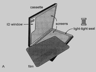
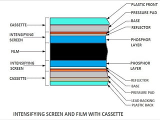
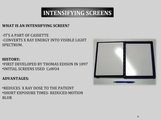
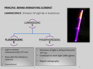
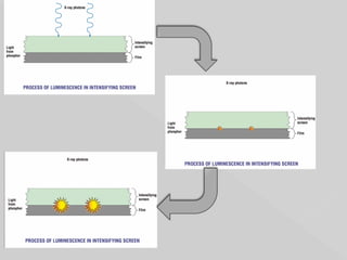
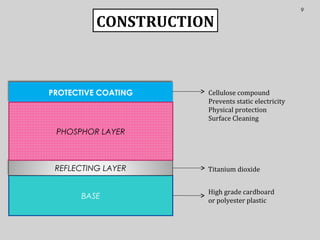
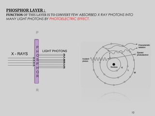
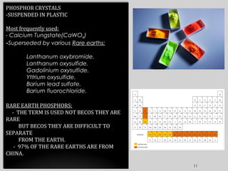
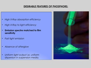
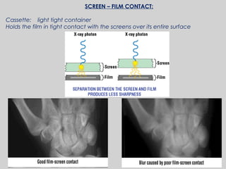
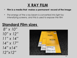
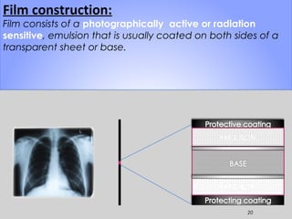
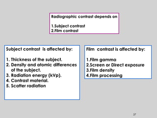
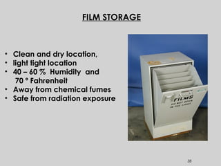


The document discusses x-ray intensifying screens and film. Intensifying screens convert x-ray energy into visible light to reduce patient dose and exposure time. They contain a phosphor layer that converts x-ray photons into many light photons. Film is light sensitive and coated with silver halide grains that form a latent image when exposed. The image is developed chemically to produce a blackened density that is measured and related to exposure on a characteristic curve. Proper storage protects the film to maintain image quality.