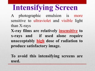
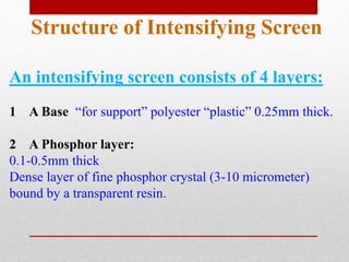
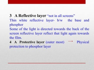
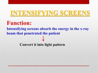
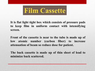
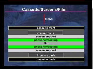
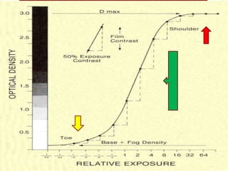
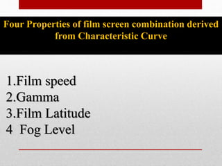
Physics overview of Film Screen
Radiography
Dr Muhammad Wasim Awan
Head Of Radiology Department
Diagnostic Rad Dept: KRL Hospital
Objectives
• Film and intensifying screen structure
• Image Formation
• Characteristic curve
• Film-screen sensitivity
Radiographic Film
Film
The radiographic images are recorded on a sheet of X-ray film.
Composition of Film:
Film consists of polyester base which is coated on both side by
emulsion.
Emulsion is suspension in gelatine of silver iodobromide crystals.
Bromide (90%) Iodide (10%)
Film is affected by storage and handling
implications as
• Mechanical pressure
• Creasing
• Static electricity
• Chemical Liquids
• Vapours
To Protect against curling and abrasions films are
coated with antistatic super coat.
Polyester Base
Silver iodobromide
Silver iodobromide
Intensifying Screen
A photographic emulsion is more
sensitive to ultraviolet and visible light
than X-rays
X-ray films are relatively insensitive to
x-rays and if used alone require
unacceptably high dose of radiation to
produce satisfactory image.
To avoid this intensifying screens are
used.
Structure of Intensifying Screen
An intensifying screen consists of 4 layers:
1 A Base “for support” polyester “plastic” 0.25mm thick.
2 A Phosphor layer:
0.1-0.5mm thick
Dense layer of fine phosphor crystal (3-10 micrometer)
bound by a transparent resin.
3 A Reflective layer “not in all screens”
Thin white reflective layer- b/w the base and
phosphor
Some of the light is directed towards the back of the
screen reflective layer reflect that light again towards
the film.
4 A Protective layer (outer most) Physical
protection to phosphor layer
Polyester base
Reflective Layer
Phosphor
Protective Layer
Intensifying Screen
• Old traditional phosphor used was Calcium Tungstate.
• Most commonly use phosphor is Lanthanum
oxybromide/oxysulphide because of increased
efficiency.
• Phosphor contain impurities (activator) which trap
energy.
• The intensity of light emitted by a screen depends of
phosphor and color of it depend on the activator.
• Films that are coated with emulsion on both sides
needs screens on both side.
INTENSIFYING SCREENS
Function:
Intensifying screens absorb the energy in the x-ray
beam that penetrated the patient
Convert it into light pattern
Advantages of intensifying screen
Film expose directly to X-rays
• More exposure is required if no screen are used
• At same density , contrast is always lower for a film
expose to x rays only rather than for the same film
exposed to light from intensifying screen
How this actually work --- as intensifying screens are
less sensitive than film to lower energy x-rays--- effect
of lower energy (scattered radaition----- contrast
Film exposed with screens to X-rays
Use of screens
• Reduce the Dose to the patient
• Reduce the Loading of tube and generator
• Allow the use of Short exposure time-- motion blur
• Allow the use of Small focal spot-- geometrical blur
SCREEN SLECTION
• Screen materials should not emit delayed
fluorescence because these would retain “memory”
of previous images .
• On reloading the cassette the pervious image would
be recorded on the new film and superimposed on
the image
It is flat light tight box which consists of pressure pads
to keep film in uniform contact with intensifying
screen.
Front of the cassette is near to the tube is made up of
low atomic number (carbon fiber) to increase
attenuation of beam so reduce dose for patient.
The back cassette is made up of thin sheet of lead to
minimize back scattered.
Pressure pads
Pressure pads
Two features of silver iodobromide crystals accounts
for photographic process:
• Small proportion of iodide as compare to bromide
distort the lattice and allows the silver ions to move
through the lattice.
• Silver iodobromide crystals posses sensitivity specks
on their surfaces
A crystal absorbs a light photon an electron liberated
which reach the sensitivity speck and its potential
energy is reduced.
When hundreds of photons have been absorbed and
enough electrons accumulated at sensitivity speck ,
these electrons attract mobile silver ions to join them
and be neutralized.
Now this forms a submicroscopic speck of silver metal
on the surface of crystal. Distribution of silver speck in
the emulsion form a latent image in the film which is
now awaited for development process
SILVER IODOBROMIDE CRYSTAL
Sensitivity
Speck
Silver ions
PHOTON
E
Changes occur with Exposure
The invisible pattern of latent images made
visible by processing.
Processing is of two types :
Manual (Old Technique)
Automatic ( Recent widely used now a days)
There are 4 steps of processing
1. DEVLOPMENT
2. FIXING
3. WASHING
4. DRYING
Step 1 Development :
Film is developed by immersion in alkaline solution
of an reducing agent which enter into the crystal and
reduce the positive silver ions to silver atoms latent
image grows into grains of metallic silver.
Crystals which carry no latent image remain
unaffected initially as bromide prevent entry of
developer. But when enough time given developer
penetrate the crystals and results in background fog
in the image.
Step 2 Fixing :
Film is now fixed with acidic solution
(Thiosulfate) which dissolve out unaffected
silver ion , so that image remain stable and
unaffected by further light
Step 3 Washing:
The film is now washed and dried under
hot air . Washing is important so that acid
doesn't turn film yellow brown as time pass
by.
Automatic processor use roller feed
system to transport film through
different solutions
• Film now caries a pattern of silver grains
corresponding to X-rays leaving the patient.
• It is a negative image
• Portion of the film where X-rays are intense
appear darkest and vice versa
• Image is viewed on illuminator
The term optic density (D) means BLACKENING of an area
depends on the number of silver grains per unit area
The degree of film blackening is :
 Directly related to intensity of radiation
 Directly related to silver grains/unit area
 Inversely related to light transmision
The measurement of film BLACKNESS is called optic Density
It is a defined as log of the ratio of incident and
transmitted light
D = log10 (incident light/transmitted light)
It is measured by Densitometer.
Why we use LOG to express density?
Because Logarithms express large differences in
number on small scale
Physiological response of human eye to different
light intensities is logarithmic
If an unexposed x-ray film is processed , it will
demonstrate the density of about 0.12 . This
density is refered as Base plus Fog Level
Base density (0.07) caused by plastic material and
dye used to make film base
Fog (0.05) : the density result form developed
unexposed silver grains
The response of a film and screen combination to X-ray
is described by characteristic curve.
It is measured using instrument sensitometer
Characteristic curve shows the relationship between
optic density and relative exposure
Primary function of characteristic curve is to describe
the contrast characteristics of the film throughout a wide
exposure range.
The area of correct exposure:
• Straight line portion
• Steepest
• Densities within the area of diagnostic interest should lie
within this range
• Density is proportional to log exposure.
Shoulder Region
• Shallow curve
• High exposure region
• Dense image
• Dark image
Toe Region
• Shallow curve
• Low exposure region
• Low density
• Bright image
Area of high exposure in which slope is
decreased is referred as SHOULDER.
The two significant characteristics of
image areas receiving exposure within
this range are that the film is quite
dark (dense) and contrast is LOW.
The part of the curve associated with
relatively low exposures is designated
the TOE, and also corresponds to the
light or low-density portions of an
image . It contribute to LOW contrast.
The highest level of contrast is
produced within a range of exposures
falling between the toe and the
shoulder. This portion of the curve is
characterized by a relatively straight
and very steep slope in comparison to
the toe and shoulder regions. In most
imaging applications, it is desirable to
expose the film within this range so as
to obtain MAXIMUMcontrast.
Latitude The exposure range over
which a film produces useful
contrast is designated the
LATITUDE.
Exposure values above the
latitude range also produce
areas with very little contrast
and have the added
disadvantage of being very
dark or dense.
An underexposed film area
contains little or no image
contrast.
Over
Exposure
Under
Exposure
Four Properties of film screen combination derived
from Characteristic Curve
1.Film speed
2.Gamma
3.Film Latitude
4 Fog Level
Speed
Speed here is loosely defined as the reciprocal of
exposure required to produce net density 1.
It is said to be High speed film when low exposure
required to produce useful density .
Factors Speed
• Increase grain size
• Modern emulsions with flat crystals
• X-ray photon energy 30-40 keV
Film Gamma (Y): Film gamma is average slope
of characteristic curve .
• It influences the amount of contrast on the
radiographic image.
• Steeper the curve higher the gamma therefore display
more contrast.
• Slope of curve increased with increased exposure and
density.
• Generally average slope is between densities 0.25-2,
• Average Film Gamma value is in range 2-3
Film Latitude: It is range of exposure that produce
net useful densities ranging from 0.25-2.
Below 0.25 gradient is too low.
Above 2 too dark to visualize on illuminator
Developer temperature cause increase rate of
chemical reaction:
• Speed
• Fog level
• Gamma
Increasing developer concentration and developing
time cause similar effects
Film Screen
Sensitivity
Film exposed alone without screen is relatively
insensitive to X-rays. In such case only 2% of
incident photon will interact with film emulsion
and form single latent image.
While using Film with intensifying screen about
30% of the photon interact which is greater
than the film alone.
During interaction X-ray photon generate 1000
light photon (intensification factor) and only
half of them reach the film.
Film and Screen Film
X-ray absorbed by phosphor, 30
Light photon produced, 18000
Light photon reaching film, 9000
Latent images produced, 90
Absorbed by film, 2
Latent images produced , 2
Flim screen physics

Flim screen physics

  • 1.
    Physics overview ofFilm Screen Radiography Dr Muhammad Wasim Awan Head Of Radiology Department Diagnostic Rad Dept: KRL Hospital
  • 2.
    Objectives • Film andintensifying screen structure • Image Formation • Characteristic curve • Film-screen sensitivity
  • 3.
    Radiographic Film Film The radiographicimages are recorded on a sheet of X-ray film. Composition of Film: Film consists of polyester base which is coated on both side by emulsion. Emulsion is suspension in gelatine of silver iodobromide crystals. Bromide (90%) Iodide (10%)
  • 4.
    Film is affectedby storage and handling implications as • Mechanical pressure • Creasing • Static electricity • Chemical Liquids • Vapours To Protect against curling and abrasions films are coated with antistatic super coat.
  • 5.
  • 6.
    Intensifying Screen A photographicemulsion is more sensitive to ultraviolet and visible light than X-rays X-ray films are relatively insensitive to x-rays and if used alone require unacceptably high dose of radiation to produce satisfactory image. To avoid this intensifying screens are used.
  • 7.
    Structure of IntensifyingScreen An intensifying screen consists of 4 layers: 1 A Base “for support” polyester “plastic” 0.25mm thick. 2 A Phosphor layer: 0.1-0.5mm thick Dense layer of fine phosphor crystal (3-10 micrometer) bound by a transparent resin.
  • 8.
    3 A Reflectivelayer “not in all screens” Thin white reflective layer- b/w the base and phosphor Some of the light is directed towards the back of the screen reflective layer reflect that light again towards the film. 4 A Protective layer (outer most) Physical protection to phosphor layer
  • 9.
  • 10.
    • Old traditionalphosphor used was Calcium Tungstate. • Most commonly use phosphor is Lanthanum oxybromide/oxysulphide because of increased efficiency. • Phosphor contain impurities (activator) which trap energy. • The intensity of light emitted by a screen depends of phosphor and color of it depend on the activator. • Films that are coated with emulsion on both sides needs screens on both side.
  • 11.
    INTENSIFYING SCREENS Function: Intensifying screensabsorb the energy in the x-ray beam that penetrated the patient Convert it into light pattern
  • 12.
    Advantages of intensifyingscreen Film expose directly to X-rays • More exposure is required if no screen are used • At same density , contrast is always lower for a film expose to x rays only rather than for the same film exposed to light from intensifying screen How this actually work --- as intensifying screens are less sensitive than film to lower energy x-rays--- effect of lower energy (scattered radaition----- contrast
  • 13.
    Film exposed withscreens to X-rays Use of screens • Reduce the Dose to the patient • Reduce the Loading of tube and generator • Allow the use of Short exposure time-- motion blur • Allow the use of Small focal spot-- geometrical blur
  • 14.
    SCREEN SLECTION • Screenmaterials should not emit delayed fluorescence because these would retain “memory” of previous images . • On reloading the cassette the pervious image would be recorded on the new film and superimposed on the image
  • 15.
    It is flatlight tight box which consists of pressure pads to keep film in uniform contact with intensifying screen. Front of the cassette is near to the tube is made up of low atomic number (carbon fiber) to increase attenuation of beam so reduce dose for patient. The back cassette is made up of thin sheet of lead to minimize back scattered.
  • 16.
  • 18.
    Two features ofsilver iodobromide crystals accounts for photographic process: • Small proportion of iodide as compare to bromide distort the lattice and allows the silver ions to move through the lattice. • Silver iodobromide crystals posses sensitivity specks on their surfaces
  • 19.
    A crystal absorbsa light photon an electron liberated which reach the sensitivity speck and its potential energy is reduced. When hundreds of photons have been absorbed and enough electrons accumulated at sensitivity speck , these electrons attract mobile silver ions to join them and be neutralized. Now this forms a submicroscopic speck of silver metal on the surface of crystal. Distribution of silver speck in the emulsion form a latent image in the film which is now awaited for development process
  • 20.
    SILVER IODOBROMIDE CRYSTAL Sensitivity Speck Silverions PHOTON E Changes occur with Exposure
  • 21.
    The invisible patternof latent images made visible by processing. Processing is of two types : Manual (Old Technique) Automatic ( Recent widely used now a days)
  • 22.
    There are 4steps of processing 1. DEVLOPMENT 2. FIXING 3. WASHING 4. DRYING
  • 23.
    Step 1 Development: Film is developed by immersion in alkaline solution of an reducing agent which enter into the crystal and reduce the positive silver ions to silver atoms latent image grows into grains of metallic silver. Crystals which carry no latent image remain unaffected initially as bromide prevent entry of developer. But when enough time given developer penetrate the crystals and results in background fog in the image.
  • 24.
    Step 2 Fixing: Film is now fixed with acidic solution (Thiosulfate) which dissolve out unaffected silver ion , so that image remain stable and unaffected by further light Step 3 Washing: The film is now washed and dried under hot air . Washing is important so that acid doesn't turn film yellow brown as time pass by.
  • 25.
    Automatic processor useroller feed system to transport film through different solutions
  • 28.
    • Film nowcaries a pattern of silver grains corresponding to X-rays leaving the patient. • It is a negative image • Portion of the film where X-rays are intense appear darkest and vice versa • Image is viewed on illuminator
  • 29.
    The term opticdensity (D) means BLACKENING of an area depends on the number of silver grains per unit area The degree of film blackening is :  Directly related to intensity of radiation  Directly related to silver grains/unit area  Inversely related to light transmision The measurement of film BLACKNESS is called optic Density
  • 30.
    It is adefined as log of the ratio of incident and transmitted light D = log10 (incident light/transmitted light) It is measured by Densitometer. Why we use LOG to express density? Because Logarithms express large differences in number on small scale Physiological response of human eye to different light intensities is logarithmic
  • 31.
    If an unexposedx-ray film is processed , it will demonstrate the density of about 0.12 . This density is refered as Base plus Fog Level Base density (0.07) caused by plastic material and dye used to make film base Fog (0.05) : the density result form developed unexposed silver grains
  • 33.
    The response ofa film and screen combination to X-ray is described by characteristic curve. It is measured using instrument sensitometer Characteristic curve shows the relationship between optic density and relative exposure Primary function of characteristic curve is to describe the contrast characteristics of the film throughout a wide exposure range.
  • 35.
    The area ofcorrect exposure: • Straight line portion • Steepest • Densities within the area of diagnostic interest should lie within this range • Density is proportional to log exposure. Shoulder Region • Shallow curve • High exposure region • Dense image • Dark image Toe Region • Shallow curve • Low exposure region • Low density • Bright image
  • 36.
    Area of highexposure in which slope is decreased is referred as SHOULDER. The two significant characteristics of image areas receiving exposure within this range are that the film is quite dark (dense) and contrast is LOW. The part of the curve associated with relatively low exposures is designated the TOE, and also corresponds to the light or low-density portions of an image . It contribute to LOW contrast. The highest level of contrast is produced within a range of exposures falling between the toe and the shoulder. This portion of the curve is characterized by a relatively straight and very steep slope in comparison to the toe and shoulder regions. In most imaging applications, it is desirable to expose the film within this range so as to obtain MAXIMUMcontrast.
  • 37.
    Latitude The exposurerange over which a film produces useful contrast is designated the LATITUDE. Exposure values above the latitude range also produce areas with very little contrast and have the added disadvantage of being very dark or dense. An underexposed film area contains little or no image contrast. Over Exposure Under Exposure
  • 38.
    Four Properties offilm screen combination derived from Characteristic Curve 1.Film speed 2.Gamma 3.Film Latitude 4 Fog Level
  • 39.
    Speed Speed here isloosely defined as the reciprocal of exposure required to produce net density 1. It is said to be High speed film when low exposure required to produce useful density . Factors Speed • Increase grain size • Modern emulsions with flat crystals • X-ray photon energy 30-40 keV
  • 40.
    Film Gamma (Y):Film gamma is average slope of characteristic curve . • It influences the amount of contrast on the radiographic image. • Steeper the curve higher the gamma therefore display more contrast. • Slope of curve increased with increased exposure and density. • Generally average slope is between densities 0.25-2, • Average Film Gamma value is in range 2-3
  • 41.
    Film Latitude: Itis range of exposure that produce net useful densities ranging from 0.25-2. Below 0.25 gradient is too low. Above 2 too dark to visualize on illuminator
  • 42.
    Developer temperature causeincrease rate of chemical reaction: • Speed • Fog level • Gamma Increasing developer concentration and developing time cause similar effects
  • 43.
  • 44.
    Film exposed alonewithout screen is relatively insensitive to X-rays. In such case only 2% of incident photon will interact with film emulsion and form single latent image. While using Film with intensifying screen about 30% of the photon interact which is greater than the film alone. During interaction X-ray photon generate 1000 light photon (intensification factor) and only half of them reach the film.
  • 45.
    Film and ScreenFilm X-ray absorbed by phosphor, 30 Light photon produced, 18000 Light photon reaching film, 9000 Latent images produced, 90 Absorbed by film, 2 Latent images produced , 2

Editor's Notes

  • #4 For understanding image formation we need to understand composition and characteristics of film and screen. In Emulsion ratio of iodobromide is important bromide is 90% and iodine is 10%
  • #6 Poly easter
  • #8 Calcium tungstate emit voilate and blue light, lanthanum oxybromide emit blue light can be used in odinary xray. Gadolinum and lan oxysulphide green light used with orthochromatic film
  • #12 X-ray films are relatively insensitive to X-rays , if these are used alone they require unacceptably high dose of radiation to produce a satisfactory image
  • #13 ( When does direct exposure to X-ray needed? When sharp image is required----- used in thin parts and where fine details required e.g Teeth & bone fracture of extremities)
  • #16 This lower atomic number material is important in lower kv such as mammography and extremity radiographs
  • #21 NOW THIS IS A LATENT (INVISIBLE ) IMAGE
  • #31 For example : Optic density of lung field in CXR is 2.0 , an area with optic density 3.0 is too dark to be viewed on standard illuminator
  • #32 We need to consider few things over here
  • #34 Characteristic curve is also known as Hurter and drrifield curve
  • #37 Curve has three distinct regions with different contrast transfer characteristics The minimum density, in the toe, is the residual density, which is observed after processing unexposed film, and is typically in the range of 0.1 to 0.2 density units. This density is produced by the inherent density of the film base material and the low-level fog in the film emulsion; it is therefore commonly referred to as the base plus fog density. The maximum density, in the shoulder, is determined by the design of the film emulsion and the processing conditions and is typically referred to as the Dmax.
  • #38 More simplified explaination of contrast and exposure BY A CONTRAST CURVE