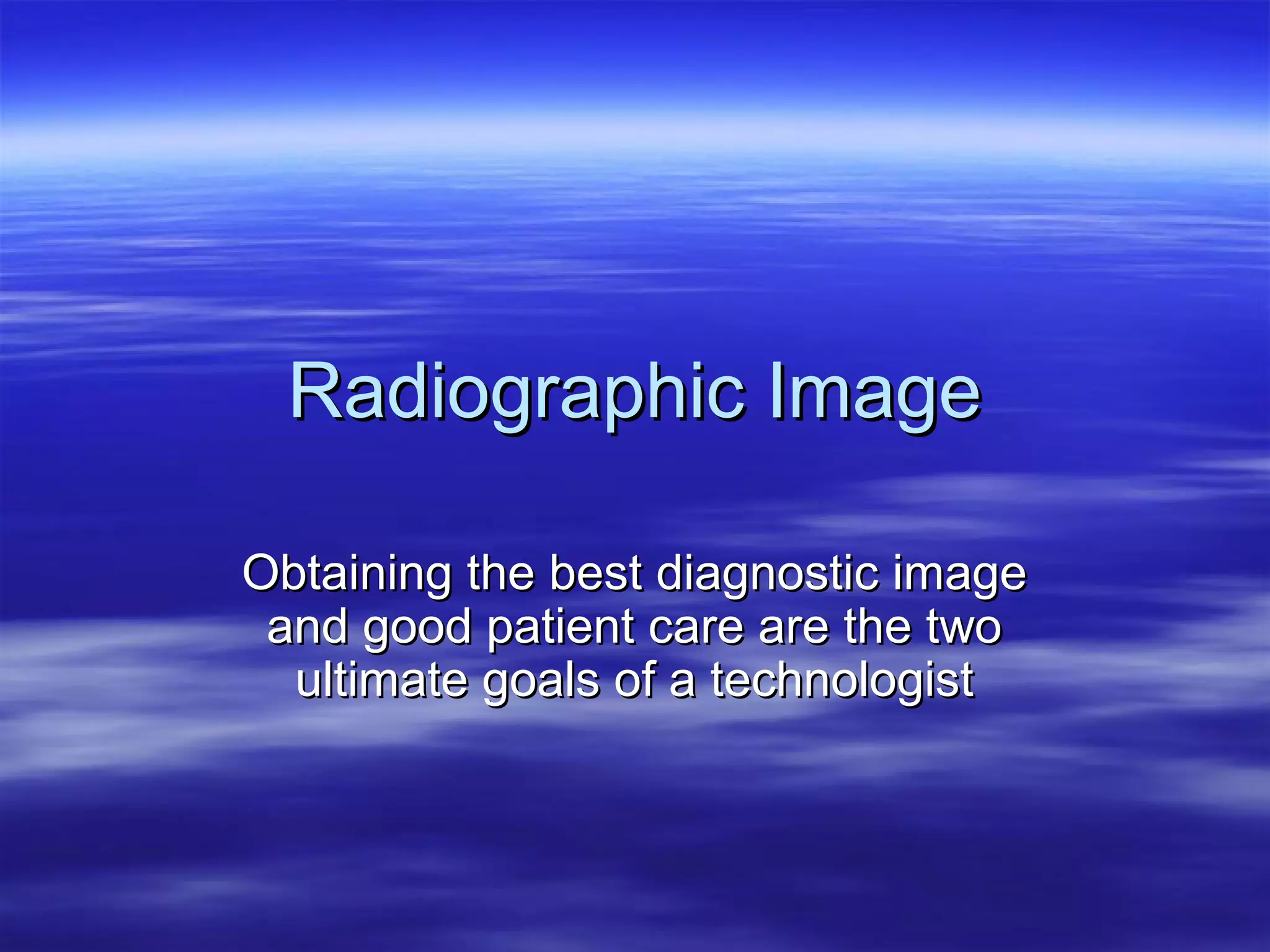
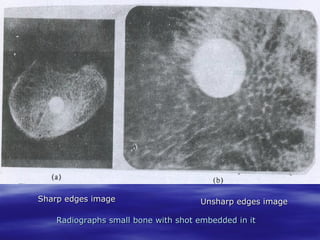
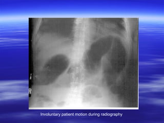
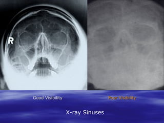
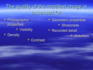
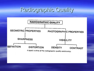
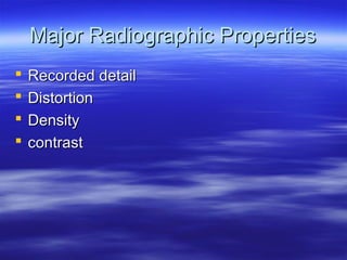
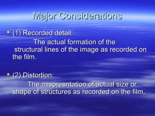
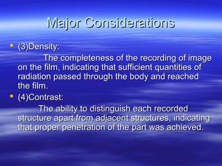
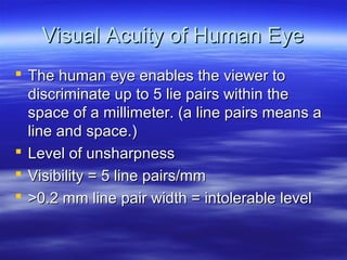
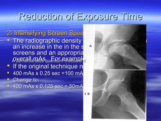
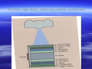
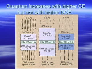
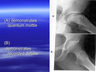
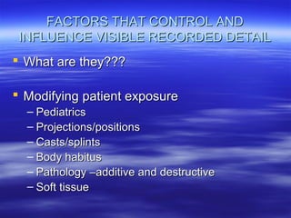
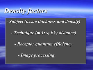
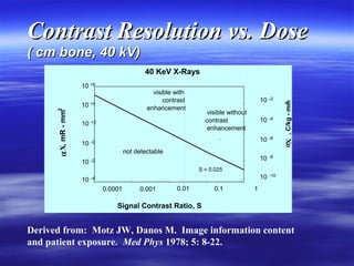
Radiographic Image
Obtaining the best diagnostic image
and good patient care are the two
ultimate goals of a technologist
Introduction
What is meant by an image that of
radiographic quality?
Sharp edges image

Unsharp edges image

Radiographs small bone with shot embedded in it
Motion blur (unsharpness)
Involuntary patient motion during radiography
Good Visibility

Poor Visibility

X-ray Sinuses
An image of radiographic quality is the one
that possesses :
 Sharpness &
 Visibility
Sharpness
 Ability to record individual lines that actually
form the image keen, distinct and thinedged.
 Sharpness is geometric properties of
radiograph.
 It is measurable factor of radiographic
quality.
Visibility
 Ability to discrete distant object
 It is photographic properties

 Visibility is quality factor of radiographic image.
 To determine the visibility, you should examine the
image for:
 Density
 Contrast
The quality of the manifest image is
assessed for
 Photographic
 Geometric properties
properties
 Sharpness
 Visibility
 Recorded detail
 Density
 distortion
 Contrast
Balance of sharpness and visibility
for radiographic quality
Radiographic Quality
Major Radiographic Properties





Recorded detail
Distortion
Density
contrast
Major Considerations
 (1) Recorded detail:
The actual formation of the
structural lines of the image as recorded on
the film.
 (2) Distortion:
The mispresntation of actual size or
shape of structures as recorded on the film,
Major Considerations
 (3)Density:
The completeness of the recording of image
on the film, indicating that sufficient quantities of
radiation passed through the body and reached
the film.
 (4)Contrast:
The ability to distinguish each recorded
structure apart from adjacent structures, indicating
that proper penetration of the part was achieved.
Visual Acuity of Human Eye
 The human eye enables the viewer to
discriminate up to 5 lie pairs within the
space of a millimeter. (a line pairs means a
line and space.)
 Level of unsharpness
 Visibility = 5 line pairs/mm
 >0.2 mm line pair width = intolerable level
Factors Influence The Sharpness
 Motion
 Material
} Measurable
 Geometry
Motion Unsharpness
 Voluntary

referred to as motion that
under conscious control of the will.

 Involuntary

motion attributed to the
physiological action of the of the body
Factors in Control of Motion
 Explanation of the procedure to the patient.
 Immobilization of the part.
Whole body immobilizers
Selected part immobilization

 Reduction of exposure time.
Immobilization aids
Immobilization of the part to avoid motional blurring.
Reduction of Exposure Time
 1- Milliamperage/Time Relationship
If the original techniqye required 100 mAs:
100 mA x 1sec =100 mAs
Change to :
400 mA x 0.25 sec = 100 mAs
Reduction of Exposure Time
2- Intensifying Screen Speeds:
 The radiographic density can be maintained with
an increase in the in the speed of intensifying
screens and an appropriate reduction in the
overall mAs . For example:
A demonstrates quantum mottle B demonstrates recorded details .
 If the original technique required 100 mAs:




400 mAs x 0.25 sec =100 mAs
Change to:
400 mAs x 0.125 sec = 50mAs with high speed screen.
Material Unsharpness
Three factors influence material
unsharpness:
 Film
 Intensifying screen.
 Film-screen contact
The three major factors influencing material unsharpness
Radiographic Film
Non screen Film:
 Has thicker emulsion.
 Two to six times faster compared with
screen-type film used with direct exposure.
 Not recommended for use with intensifying
screen.
Parallax
Radiographic Film
Screen -Type Film
 Has thinner emulsion.
 Slow in speed when used with direct
exposure.
 There is a significant increase in speed
when used with intensifying screen.
Comparison of typical exposure factors in an
AP projection of the knee(12:1moving grid)
– Type of radiography
exposure factors
– --------------------------------------------------------------– Ultrahigh speed screens

20mAs(100mAx0.2 sec at 60kvp)

– High speed screens

30mAs(100mAx0.3 sec at 60kvp)

– Par speed screens

60mAs(100mAx0.6 sec at 60kvp)

– Slow speed screen

120mAs(100mAx1.2 sec at 60kvp)

– Direct exposure

4800mAs(100mAx12 sec at 60kvp)
Quantum Mottle
 Radiographic noise produced by the
random interaction of x-rays with an
intensifying screen. This effect is more
noticeable when very high rare-earth
systems are used at high kvp.
Quantum Mottle (image noise)
 Occurs more often when fast screens and high
kvp techniques are used.
 Screen speed increased because of:
 1- High absorb percentage of x-ray this is called
detective quantum efficiency (DQE).
 2- The amount of light emitted for each x-ray
absorbed is also high. This is called conversion
efficiency (CE)
Quantum increases with higher CE
but not with higher DQE.
(A) demonstrates
quantum mottle

(B)
demonstrates
recorded details
Diffusion of light decrease image
sharpness
Advantages Using Nonscreen Film
 Improved Recorded details, Sharpness
Resolution.
 Production of longer scale contrast.
 Increase exposure latitude.
 Lack of artifacts associated with dirty
screen.
However ,with increased of radiation dose.
Comparison screen speed to image
details
Poor film screen contact
Poor film-screen contact
Good film-screen contact
DENSITY
 CONTROLLING FACTORS?

 INFLUENCING FACTORS?
CONTRAST
 Subject Contrast

 Film (IR) Contrast
CONTRAST
 CONTROLLING FACTORS?

 INFLUENCING FACTORS?
FACTORS THAT CONTROL AND
INFLUENCE VISIBLE RECORDED DETAIL
 What are they???
 Modifying patient exposure
– Pediatrics
– Projections/positions
– Casts/splints
– Body habitus
– Pathology –additive and destructive
– Soft tissue
Density factors
- Subject (tissue thickness and density)
- Technique (mA; s; kV; distance)
- Receptor quantum efficiency
- Image processing
Improved Quantum Efficiency
100
80
60
40
20
0
1919

1925

1941

1955

1981

% Relative Dose

1991

1999
Contrast Resolution vs. Dose
( cm bone, 40 kV)

40 KeV X-Rays

10

visible with
contrast
enhancement

10

10

`

not detectable
10

-2

-4

-6

10

-0

-2

10

visible without
contrast
enhancement

+2

10

10

-8

10

+4

-10

2
αX , C/kg - mm

X, mR - mm2

10 +6

S = 0.025

10

-4

0.0001

0.001

0.01

0.1

1

Signal Contrast Ratio, S

Derived from: Motz JW, Danos M. Image information content
and patient exposure. Med Phys 1978; 5: 8-22.
Contrast sources
Subject
Signal
Exposure energy
Receptor
Processing
Radiopacity and radiolucency are relative
terms. The central gray squares are all of
the same density.
The left triangle seems lighter than the right one.
This is only an illusion - they are equal in density.
Kanisza triangle: optical illusions can occur
when interpreting black and white images.

Radiographic image4

  • 1.
    Radiographic Image Obtaining thebest diagnostic image and good patient care are the two ultimate goals of a technologist
  • 2.
    Introduction What is meantby an image that of radiographic quality?
  • 3.
    Sharp edges image Unsharpedges image Radiographs small bone with shot embedded in it
  • 4.
  • 5.
    Involuntary patient motionduring radiography
  • 6.
  • 8.
    An image ofradiographic quality is the one that possesses :  Sharpness &  Visibility
  • 9.
    Sharpness  Ability torecord individual lines that actually form the image keen, distinct and thinedged.  Sharpness is geometric properties of radiograph.  It is measurable factor of radiographic quality.
  • 10.
    Visibility  Ability todiscrete distant object  It is photographic properties  Visibility is quality factor of radiographic image.  To determine the visibility, you should examine the image for:  Density  Contrast
  • 11.
    The quality ofthe manifest image is assessed for  Photographic  Geometric properties properties  Sharpness  Visibility  Recorded detail  Density  distortion  Contrast
  • 12.
    Balance of sharpnessand visibility for radiographic quality
  • 13.
  • 14.
  • 15.
    Major Considerations  (1)Recorded detail: The actual formation of the structural lines of the image as recorded on the film.  (2) Distortion: The mispresntation of actual size or shape of structures as recorded on the film,
  • 16.
    Major Considerations  (3)Density: Thecompleteness of the recording of image on the film, indicating that sufficient quantities of radiation passed through the body and reached the film.  (4)Contrast: The ability to distinguish each recorded structure apart from adjacent structures, indicating that proper penetration of the part was achieved.
  • 17.
    Visual Acuity ofHuman Eye  The human eye enables the viewer to discriminate up to 5 lie pairs within the space of a millimeter. (a line pairs means a line and space.)  Level of unsharpness  Visibility = 5 line pairs/mm  >0.2 mm line pair width = intolerable level
  • 19.
    Factors Influence TheSharpness  Motion  Material } Measurable  Geometry
  • 20.
    Motion Unsharpness  Voluntary referredto as motion that under conscious control of the will.  Involuntary motion attributed to the physiological action of the of the body
  • 21.
    Factors in Controlof Motion  Explanation of the procedure to the patient.  Immobilization of the part. Whole body immobilizers Selected part immobilization  Reduction of exposure time.
  • 22.
  • 23.
    Immobilization of thepart to avoid motional blurring.
  • 24.
    Reduction of ExposureTime  1- Milliamperage/Time Relationship If the original techniqye required 100 mAs: 100 mA x 1sec =100 mAs Change to : 400 mA x 0.25 sec = 100 mAs
  • 25.
    Reduction of ExposureTime 2- Intensifying Screen Speeds:  The radiographic density can be maintained with an increase in the in the speed of intensifying screens and an appropriate reduction in the overall mAs . For example: A demonstrates quantum mottle B demonstrates recorded details .  If the original technique required 100 mAs:    400 mAs x 0.25 sec =100 mAs Change to: 400 mAs x 0.125 sec = 50mAs with high speed screen.
  • 26.
    Material Unsharpness Three factorsinfluence material unsharpness:  Film  Intensifying screen.  Film-screen contact
  • 27.
    The three majorfactors influencing material unsharpness
  • 28.
    Radiographic Film Non screenFilm:  Has thicker emulsion.  Two to six times faster compared with screen-type film used with direct exposure.  Not recommended for use with intensifying screen.
  • 29.
  • 30.
    Radiographic Film Screen -TypeFilm  Has thinner emulsion.  Slow in speed when used with direct exposure.  There is a significant increase in speed when used with intensifying screen.
  • 31.
    Comparison of typicalexposure factors in an AP projection of the knee(12:1moving grid) – Type of radiography exposure factors – --------------------------------------------------------------– Ultrahigh speed screens 20mAs(100mAx0.2 sec at 60kvp) – High speed screens 30mAs(100mAx0.3 sec at 60kvp) – Par speed screens 60mAs(100mAx0.6 sec at 60kvp) – Slow speed screen 120mAs(100mAx1.2 sec at 60kvp) – Direct exposure 4800mAs(100mAx12 sec at 60kvp)
  • 32.
    Quantum Mottle  Radiographicnoise produced by the random interaction of x-rays with an intensifying screen. This effect is more noticeable when very high rare-earth systems are used at high kvp.
  • 33.
    Quantum Mottle (imagenoise)  Occurs more often when fast screens and high kvp techniques are used.  Screen speed increased because of:  1- High absorb percentage of x-ray this is called detective quantum efficiency (DQE).  2- The amount of light emitted for each x-ray absorbed is also high. This is called conversion efficiency (CE)
  • 34.
    Quantum increases withhigher CE but not with higher DQE.
  • 35.
  • 36.
    Diffusion of lightdecrease image sharpness
  • 37.
    Advantages Using NonscreenFilm  Improved Recorded details, Sharpness Resolution.  Production of longer scale contrast.  Increase exposure latitude.  Lack of artifacts associated with dirty screen. However ,with increased of radiation dose.
  • 38.
    Comparison screen speedto image details
  • 39.
  • 41.
  • 42.
  • 43.
  • 44.
  • 45.
  • 46.
    FACTORS THAT CONTROLAND INFLUENCE VISIBLE RECORDED DETAIL  What are they???  Modifying patient exposure – Pediatrics – Projections/positions – Casts/splints – Body habitus – Pathology –additive and destructive – Soft tissue
  • 47.
    Density factors - Subject(tissue thickness and density) - Technique (mA; s; kV; distance) - Receptor quantum efficiency - Image processing
  • 48.
  • 49.
    Contrast Resolution vs.Dose ( cm bone, 40 kV) 40 KeV X-Rays 10 visible with contrast enhancement 10 10 ` not detectable 10 -2 -4 -6 10 -0 -2 10 visible without contrast enhancement +2 10 10 -8 10 +4 -10 2 αX , C/kg - mm X, mR - mm2 10 +6 S = 0.025 10 -4 0.0001 0.001 0.01 0.1 1 Signal Contrast Ratio, S Derived from: Motz JW, Danos M. Image information content and patient exposure. Med Phys 1978; 5: 8-22.
  • 50.
  • 52.
    Radiopacity and radiolucencyare relative terms. The central gray squares are all of the same density.
  • 53.
    The left triangleseems lighter than the right one. This is only an illusion - they are equal in density.
  • 54.
    Kanisza triangle: opticalillusions can occur when interpreting black and white images.