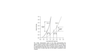
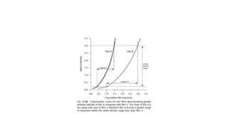
SlideShare a Scribd company logo
1 of 87
Dr. Amit Kumar Bansal
bansaldentalworld@gmail.com
CHARACTERSTICS AND
TION GEOMETRY
CONTENTS
• Definition of ideal radiograph
• Image chracterstics
• Radiographic density
• Radiographic contrast
• Film fog
• Film Speed
• Film lattitude
• Ideal Projection geometry
• Image sharpness
• Image magnificaton
• Image distortion
• Parelleling technique
• Bisecting technique
• Slob technique
DEFINITION
• An Ideal Radiograph is one that provides a great deal of
information, the image exhibits proper density and contrast,
have sharp outlines and are of the same shape and size as
the object being radiographed.
• In HM Worth’s words; “An Ideal Radiograph is one which
has desired density and overall blackness and which shows
the part completely without distortion with maximum
details and has the right amount of contrast to make the
details fully apparent”.
IMAGE CHARACTERSTICS &PROJECTION
GEOMETRY
• Characteristic of ideal radiograph include both visual & geomatric
characteristics.
• Visual characteristic:
• Density.
• Contrast.
• Speed
• latitude
• Geometric characteristics:
• Sharpness or resolution
• Magnification.
• Distortion.
IMAGE CHARACTERSTICS
The major imaging characteristics of x-
ray film are
1. Radiographic density
2. Radiographic contrast
3. Radiographic speed
4. Film latitude
5. Radiographic Noise
A diagnostic (ideal) radiograph provides a great deal of information:
• the images exhibit proper density and contrast
• have sharp outlines and
• of the same shape and size as the object
RADIOGRAPHIC DENSITY
• When a film exposed by x- ray beam by light or screen –film
combinations & then processed.
• silver hallide crystals in emulsion that were
stuck by photons & converted to grains of metallic silver.
 Silver grains block the transmission of light from view box- -give film
its dark appearance.
The overall degree of darkening of an exposed film is
referred to as radiographic density.
Measured as the optical density of an area of an x-ray film, where,
OPTICAL DENSITY = Log 10 Io/It
Io - intensity of incident light (from view box)
It - intensity of light transmitted through the film
The measurement of film density is also a measure of the opacity of the
film.
Optical density is 0 means 100% of the light is transmitted
Optical density is 1 means 10% of the light is transmitted
Optical density is 2 means 1% of the light is transmitted.
A film is of greatest diagnostic value when the structures of
interest are imaged on the relatively straight portion of the graph,
between 0.6 to 3.0 optical density units.
Gross fog or base plus fog: an unexposed film, when processed, shows
some density caused by the inherent density of the base, added tint and
the development of unexposed silver halide crystals.
The optical density of gross fog is 0.2 to 0.3
FILM DENSITY
• White areas (e.g., metallic restorations) have no density and
black areas (air spaces)have maximum density.
• The areas in between these
two extremes
(tooth structure bone)
are represented by
various shades of gray.
FILM DENSITY
• Radiolucent:
Refers to high film density , which appears in a range from dark
grey to black. Soft tissue air spaces and pulp tissue , all of which have
low object density ,appears as radiolucent areas on a film.
• Radiopaque:
Refers to areas with low density which appears in a range from light
grey to white on the film. (The white areas of film are actually clear
but appear white when the light from passes through the film).
• Structures with high object density, such as enamel bone and metallic
restorations will appears radiopaque.
 The overall density of film affects the
diagnostic value of the film.
 Only the center film below has proper density.
 The one on left is too light (low density),
the one on right is too dark (high density);
both of these film are non diagnostics.
Radiographic density is influenced by
Exposure
Subject thickness
Subject Density
Exposure factors :
The overall film density depends on number of
photons absorbed by the film emulsion.
Increasing the mA, kVp,or exposure time
increases the no of photons reaching the film.
Increase the density of radiograph
reducing the distance b/w focal spot & film
also increase film density.
OBJECT THICKNESS
• Determined by type of material(metals,
tooth structure, composite) and by amount of material. Metallic
restorations have higher object density than tooth structure.
Film density decreases (film gets lighter)when object density
increases, assuming no changes are made in the exposures factors.
In the film at right,
the post and core in
each tooth has a high
object density,
resulting in low film
density.
FILM DENSITY INFLUNCED BY
• FILM FOG: this is an increased film density resulting from causes
other than exposure to the primary x-ray beam.
• This includes scatter radiation, improper safe lighting, improper film
storage, and using expired film.
• All of these things will cause extra silver halllide crystals on the film
to be converted to black metallic silver, resulting in an overall
increase in the film density and making the film less diagnostic.
CONTRAST
Contrast refers to the difference in film densities
between various regions on a radiograph. Structure
with different object densities produce image with
different film densities.
HIGH CONTRAST
• High contrast implies that image that shows
both light areas and dark areas.
 also known as short gray scale contrast.
 Few shades of grey are present between the
black and white images on the film.
 Best for caries detection
LOW CONTRAST
• A radiographic image composed only of light gray and dark gray
zones.
• Long gray scale of contrast.
• It is best for periapical or periodontal evalution.
SUBJECT CONTRAST
• Range of characteristics of subject that influences radiograph
contrast.
• Largely influenced by-
• Subject thickness
• Density
• Atomic number
• Subject contrast of a patient’s head and neck exposed in a
cephalometric view is high.
• Dense regions of the bone and teeth absorb most of incident radiation;
whereas less dense soft tissue facial profile transmits most of
radiation.
Contrast influenced by
• Also influenced by beam energy and intensity.
• The energy of x-ray beam,selected by kVp,
influences image contrast.
 kVp: kvp controls the energy of the x-rays.
 The higher the kVp,the more easily the x-rays pass through objects
in their path,resulting in many shades of gray(low contrast).
 At lower kvp settings it is harder for x-rays to pass through objects
with higher object densities resulting in a high contrast.
Radiograph of a step wedge made at 40 to 100 kVp. As the kVp inc.,
the mA is reduced
To maintain the uniform middle step density .low contast with high
kVp.
FILM CONTRAST
Describes the capacity of radiographic films to display
differences in subject contrast,
A high-contrast film reveals areas of small difference in
subject contrast
Properly exposed films have more contrast than underexposed (light
films)
Film processing influences film contrast. Film contrast is
maximized by optimal film processing conditions.
Improper handling of the film, such as
a) Storage at too high a temperature,
b) Exposure to excessively bright safe, degrades film lights
contrast.
c) Light leaks in the darkroom
Film fog
Fog on an x-ray film results in increase film density in turn reduces the
film contrast. Common causes of film fog are
a) Improper safelighting
b) Storage of film at too high a temperature, and
c) Development of film at an excessive temperature or for a prolonged
period.
Film fog can be minimized by proper film processing and
storage.
C) Scattered radiation:
Scattered radiation results from photons that have interacted
with the subject by compton or coherent interactions.
Scattered radiation causes fogging of a radiograph.
Scattered radiation can be reduced by
a) Use a relatively low kVp
b) Collimate the beam to the size of the film, and
c) Use grids in extraoral radiography.
3) RADIOGRAPHIC SPEED:
Refers to the amount of radiation required to produce an
image of a standard density.
Film speed is expressed as reciprocal of exposure (in roentgens)
required to produce an optical density of 1 above gross fog.
A fast film requires a relatively low exposure to produce a density
of 1, whereas a slower film requires a longer exposure for
processed film to have same density.
Controlled largely by the size of the silver halide grains and their
silver content.
Speed of dental intraoral x-ray film is indicated by letter designating a
Particular group.
The films most often used are kodak ultraspeed (group D) and kodak
insight (group E or F).
 Insight film is preferred because it requires only about half the
exposure of ultra speed film and offers comparable contrast and
resolution.
F-speed film is faster than the D-speed film because tabular crystal
grains are used in the emulsion of F-speed film.
Film speed can be increased by processing the film at a higher
temperature
Processing in depleted solutions can lower the effective speed.
It is always preferable to use fresh processing solutions and follow
the recommended processing time and temperature.
4) FILM LATITUDE:
Measure of the range of exposure that can be recorded as
distinguishable densities on a film.
 A film optimized to display a wide lattitude can record subject with
wide range of subject contrast.
A film with a characteristic curve that has a long straight-line position
and a shallow slope has a wide latitude.
Wide latitude have lower contrast
Wide-latitude films are useful when both the
osseous structures of the skull and soft tissues of
the facial region must be recorded.
A high kVp produces images with a wide
latitude and low contrast. Recommended for
imaging structures with a wide range of subject
densities.
RADIOGRAPHIC NOISE
Appearance of uneven density of a uniformly
exposed radiographic film.
Seen on a small area of film as localized
variations in density.
Primary causes of radiographic noise are
A) Radiographic mottle
B) Radiographic artifact
A)Radiographic Mottle:-
1. On intraoral dental film, mottle may be seen as film graininess
2. Graininess is most evident when high temperature processing is
used.
3. Mottle is also evident when the film is used with fast intensifying
screens
Two important causes of radiographic mottle
in intensifying screens are
1) Quantum mottle – caused by a fluctuation
in the number of photons per unit of the
beam cross-sectional area absorbed by the
intensifying screens.
2) Screen structure mottle is graininess
caused by screen phosphors.
B) Radiographic Artifacts:
Radiographic artifacts are defects caused by
1. Errors in film handling, such as finger prints or bends in the film,
2. Errors in film processing, such as splashing developer or fixer on a
film or marks or scratches from rough handling
IDEAL PROJECTION GEOMTERY
The basic principles of projection geometry
(shadow casting)
 The focal spot should be as small as possible
 Focal spot to object distance should be as long as possible.
 Object to film distance should be as small as possible.
 Long axis of object and film planes should be parallel.
 X-ray beam should strike the object and film planes at right angles.
 There should be no movement of the tube, film or patient during exposure
( given by Manson and Lincoln)
IMAGE SHARPNESS
• Measures how well the details (boundaries/edges) of an
object are reproduced on a radiograph.
• The fuzzy unclear area that surround the image is termed
penumbra.
(pene=almost + umbra= shadow)
• Def.: Zone of unsharpness along the edge of images in a
radiograph
• The larger the penumbra, the less sharp the image will be
Penumbra Umbra
(complete shadow)
Target
(focal spot)
• Three methods exits for minimizing this loss of image clarity and
improving the quality of radiographs;
• Use as small an effective focal spot:
• Size of effective focal spot is a function of angel of target with respect
to long axis of electron beam.
• Use as small an effective focal spot as practical. Dental x-ray machines should have a nominal
focal spot size of 1.0 mm or less. Some tubes used in extraoral radiography have effective focal
spots measuring 0.3 mm, which greatly adds to image clarity. X-ray tube manufacturers use as
small an effective focal spot size as is consistent with the requirements for heat dissipation. As
described in Chapter 1, the size of the effective focal spot is a function of the angle of the target
with respect to the long axis of the electron beam. A large angle distributes the electro beam over a
larger surface and decreases the heat generated per unit of target area, thus prolonging tube life.
However, this results in a larger effective focal spot and loss of image clarity (Fig. 5-2). A small
angle has a greater wearing effect on the target but results in a smaller effective focal spot,
decreased un sharpness, and increased image sharpness and resolution. This angle of the face of
the target to the central x-ray beam is usually between 10 and 20 degree
• . Increase the distance between the focal spot and the object by using a long,
open-ended cylinder: Fig. 5-3 shows how
increasing the focal spot-to-object distance reduces
• image blurring by reducing the divergence of the x-
• ray beam. The longer focal spot-to-object distance
• minimizes blurring by using photons whose path
• are almost parallel. The benefits of using a long focal
• spot-to-object distance support the use of long,
• open-ended cylinders as aiming devices on dental x-
• ray machines.3.
Decreasing the
Decreasing the angle ot the target perpendicular to the long
axis ot the electron beam decreases the actual focal spot
size and decreases heat dissipation and thereby tube life. It
also decreases the effective focal spot size, thus increasing
• Minimize the distance between the object and the film. Fig.
• 5-4 shows that as the object-to-film distance is
• reduced, the unsharpness decreases, resulting in
• enhanced image clarity. This is the result of mini-
• mizing the divergence of the x-ray photons
IMAGE SIZE DISTORTION
• image size distortion (magnification) is the increase in size of the
image on the radiograph compared with the actual size of the object.
The divergent paths of photons in an x-ray beam cause enlargement
of the image on a radiograph. Image size distortion results from the
relative distances of the focal spot-to-film and object-to-film (see
Figs. 5-3 and 5-4). Accordingly,
• increasing the focal spot-to-film distance and decreasing the object-
to-film distance minimizes image magnification. The use of a long,
open-ended cylinder as a
• aiming device OIY an x-ray machme thus reduces the
• magnification of images on a periapical view. Further-
• more, as mentioned above, this technique also
• improves image clarity by increasing the distance
• between the focal spot and object.
• Image shape distortion is the result of unequal magnification of different parts of the same object. This situation arises when not all the
parts of an object are at the same focal spot-to-object distance. The physical shape of the object may often prevent its optimal
orientation, resulting in some shape distortion. Such phenomenon is seen by the differences in appearance of the image on a radiograph
compared with the true shape. To minimize shape distortion, the practitioner
• should make an effort to align the tube, object, and film tarefully, using the following guidelines:
• 1. Position the film parallel to the long axis of the object.Image shape distortion is minimized when the long axes of the film and tooth are
parallel. Fig. 5-5 showsthat the central ray of the x-ray beam is perpendicular to the film, but the object is not parallel to the film. The
resultant image is distorted because of the unequal distances of the various parts of the object from the film. This type of shape distortion
is called foreshortening because it causes the radiographic
• image to be shorter than the object. Fig. 5-6 show me sltuauon wnen me x-ray oeam IS onentea at ngnt angles to the object but not to the
film. This result in elongation, with the object appearing longer on the film than its actual length
• Orient the central ray perpendicular to the object and film.
• Image shape distortion occurs if the object and film
• are parallel but the central ray is not directed at right
• angles to each. This is most evident on maxillary
• molar projections (Fig. 5-7). If the central ray is ori-
• ented with an excessive vertical angulation, the
• palatal roots appear disproportionately longer than
• the buccal roots.
• The practitioner can prevent distortion errors by
• aligning the object and film parallel with each other
• and the central ray perpendicular to both.
• Increase the distance between the focal spot and the object by using
a long,open ended cylinder:
• increase the focal spot to object distance
reduces image
• Principle : The central concept of the paralleling is that “ the x-ray
receptor is supported parallel to the long axis of the teeth and the
central ray of the x-ray beam is directed at right angles to the teeth
and receptors.”
• Minimizes geometric distortion and presents the teeth and supporting
bone in their true anatomic relationship.
PENEUMBRA
• (pene=almost + umbra= shadow)
• Def.: Zone of unsharpness along the edge of images in a
radiograph
• The larger the penumbra, the less sharp the image will be
Penumbra Umbra
(complete shadow)
Target
(focal spot)
• Sharpness influenced by:
1. Focal spot size
2. Source–object (teeth) distance
3. Object (teeth)-film distance
4. Intensifying screens
5. Film crystal size
6. Motion
Decrease focal spot size, increase
sharpness
Target Object Umbra Penumbra
If the lack of parallelism
does not exceed 20,the
radiograph is generally
acceptable.
Place 1 or 2 cotton
rolls on bite block
Increase the vertical
angulation by 5 to 15
degree.
Modifications
For maxilla, place the film
on far side of the film
• For mandible, place film
between the tori and
tongue
ADVANTAGES DISADVANTAGES
Accuracy
Difficult for a
beginner
Simplicity Discomfort
Duplication
Patient
Compliance
BISECTINGANGLE TECHNIQUE
• The bisecting-angle technique is based on a simple geometric
theorem, Cieszynski ’ s rule of isometry, which states that two
triangles are equal when they share one complete side and have two
equal angles.
• Receptor is positioned as close as possible to the lingual surface of
the teeth, resting in the palate or in the floor of the mouth.
• The plane of the receptor and the long axis of the teeth form an angle,
with its apex at the point where the receptor is in contact with the
teeth. An imaginary line that biAsects this angle, direct the central ray
of the beam at right angles to this bisector.
ADVANTAGES
• No film holder required.
• Better technique when anatomical variations hinder paralleling tech.
• Decreased exposure time.
DISADVANTAGES
• To reproduce the length of each root of a multi-rooted tooth
accurately, the central beam must be angled differently for each root.
(Inaccurate)
• Another limitation of this technique is that the alveolar ridge often
projects more coronally than its true position, thus distorting the
apparent height of the alveolar bone around the teeth.
• to obtain three-dimensional information of location of an object.
• The right-angle (or cross-section) technique
• The tube shift technique
SLOB TECHNIQUE
 IMAGE CHARACTERSTICS AND PROJECTION GEOMETRY

More Related Content

What's hot

Latent Image formation & Dark room Chemistry.pptx
Latent Image formation & Dark room Chemistry.pptxLatent Image formation & Dark room Chemistry.pptx
Latent Image formation & Dark room Chemistry.pptxssuser71d7b1
 
Digital radiography
Digital radiographyDigital radiography
Digital radiographyharibudke
 
Collimation & filtration
Collimation & filtrationCollimation & filtration
Collimation & filtrationPOOJAKUMARI277
 
Radiographic Latent Image .pptx
Radiographic Latent Image .pptxRadiographic Latent Image .pptx
Radiographic Latent Image .pptxDr. Dheeraj Kumar
 
Dental radiology ppt
Dental radiology pptDental radiology ppt
Dental radiology pptAbeer Tohmazy
 
Intensifying screen avinesh shrestha
Intensifying screen avinesh shresthaIntensifying screen avinesh shrestha
Intensifying screen avinesh shresthaAvinesh Shrestha
 
radiology-x-ray film & screens
 radiology-x-ray film & screens radiology-x-ray film & screens
radiology-x-ray film & screensParth Thakkar
 
Quality of radiograph by dr ashok
Quality of radiograph by dr  ashokQuality of radiograph by dr  ashok
Quality of radiograph by dr ashokAshok Sharma
 
Radiographic film
Radiographic filmRadiographic film
Radiographic filmRad Tech
 
Contrast
ContrastContrast
Contrastmr_koky
 
X ray films and their development by amit kumar
X ray films and their development by amit kumarX ray films and their development by amit kumar
X ray films and their development by amit kumaramithoodamit
 
Intensifying screens & films
Intensifying screens & filmsIntensifying screens & films
Intensifying screens & filmsVishwanath R S
 

What's hot (20)

Latent Image formation & Dark room Chemistry.pptx
Latent Image formation & Dark room Chemistry.pptxLatent Image formation & Dark room Chemistry.pptx
Latent Image formation & Dark room Chemistry.pptx
 
Digital radiography
Digital radiographyDigital radiography
Digital radiography
 
Dental radiography
Dental radiographyDental radiography
Dental radiography
 
Grids
GridsGrids
Grids
 
Collimation & filtration
Collimation & filtrationCollimation & filtration
Collimation & filtration
 
Radiographic Latent Image .pptx
Radiographic Latent Image .pptxRadiographic Latent Image .pptx
Radiographic Latent Image .pptx
 
X ray film
X ray film X ray film
X ray film
 
PROCESSING
PROCESSINGPROCESSING
PROCESSING
 
Dental radiology ppt
Dental radiology pptDental radiology ppt
Dental radiology ppt
 
Intensifying screen avinesh shrestha
Intensifying screen avinesh shresthaIntensifying screen avinesh shrestha
Intensifying screen avinesh shrestha
 
radiology-x-ray film & screens
 radiology-x-ray film & screens radiology-x-ray film & screens
radiology-x-ray film & screens
 
Ideal radiography
Ideal radiographyIdeal radiography
Ideal radiography
 
Quality of radiograph by dr ashok
Quality of radiograph by dr  ashokQuality of radiograph by dr  ashok
Quality of radiograph by dr ashok
 
Xeroradiography
XeroradiographyXeroradiography
Xeroradiography
 
Radiographic film
Radiographic filmRadiographic film
Radiographic film
 
Radiographic grids
Radiographic gridsRadiographic grids
Radiographic grids
 
Contrast
ContrastContrast
Contrast
 
X ray films and their development by amit kumar
X ray films and their development by amit kumarX ray films and their development by amit kumar
X ray films and their development by amit kumar
 
Orthopantomography
OrthopantomographyOrthopantomography
Orthopantomography
 
Intensifying screens & films
Intensifying screens & filmsIntensifying screens & films
Intensifying screens & films
 

Similar to IMAGE CHARACTERSTICS AND PROJECTION GEOMETRY

Image characteristics
Image characteristicsImage characteristics
Image characteristicsBhargavi Sood
 
Image characteristics,latent image,film processing.
Image characteristics,latent image,film processing.Image characteristics,latent image,film processing.
Image characteristics,latent image,film processing.DENTALBLOG
 
IDEAL RADIOGRAPH 1.pptx
IDEAL RADIOGRAPH 1.pptxIDEAL RADIOGRAPH 1.pptx
IDEAL RADIOGRAPH 1.pptxDrMeghaBahal
 
factor affecting quality of radiograph
factor affecting quality of radiographfactor affecting quality of radiograph
factor affecting quality of radiographIslamfaiq9
 
Medical Equipment lec 7 Radiography detectors
Medical Equipment lec 7 Radiography detectorsMedical Equipment lec 7 Radiography detectors
Medical Equipment lec 7 Radiography detectorscairo university
 
Image quality
Image qualityImage quality
Image qualityairwave12
 
Radiographic Image contrast & image resolution
Radiographic Image contrast & image resolutionRadiographic Image contrast & image resolution
Radiographic Image contrast & image resolutionNitish Virmani
 
Photographic Characteristic of X ray Film.pptx
Photographic Characteristic of X ray Film.pptxPhotographic Characteristic of X ray Film.pptx
Photographic Characteristic of X ray Film.pptxPrashantVerma227710
 
Revision lecture 1
Revision lecture 1Revision lecture 1
Revision lecture 1mr_koky
 
Radiographic Quality, Density, Contrast, Detail, Radiographic Accessories.pptx
Radiographic Quality, Density, Contrast, Detail, Radiographic Accessories.pptxRadiographic Quality, Density, Contrast, Detail, Radiographic Accessories.pptx
Radiographic Quality, Density, Contrast, Detail, Radiographic Accessories.pptxDrKanteshkumarMJ
 
radio cassettes and screens.pptx
radio cassettes and screens.pptxradio cassettes and screens.pptx
radio cassettes and screens.pptxrohanjohnjacob
 
Densitometry, transmittance, opacity, optical density, characteristics curve ...
Densitometry, transmittance, opacity, optical density, characteristics curve ...Densitometry, transmittance, opacity, optical density, characteristics curve ...
Densitometry, transmittance, opacity, optical density, characteristics curve ...AsaberaAkle
 
sensitrometry and characteristic curve poonam Rijal 24th june.pptx
sensitrometry and characteristic curve poonam Rijal 24th june.pptxsensitrometry and characteristic curve poonam Rijal 24th june.pptx
sensitrometry and characteristic curve poonam Rijal 24th june.pptxPoonamRijal
 
Aerial photographic film
Aerial photographic filmAerial photographic film
Aerial photographic filmchandan00781
 
Image characteristics of x ray film
Image characteristics of x ray filmImage characteristics of x ray film
Image characteristics of x ray filmYashawant Yadav
 
characteristics of films - graininess, density, speed, contrast
characteristics of films - graininess, density, speed, contrastcharacteristics of films - graininess, density, speed, contrast
characteristics of films - graininess, density, speed, contrastkarthi keyan
 

Similar to IMAGE CHARACTERSTICS AND PROJECTION GEOMETRY (20)

Image characteristics
Image characteristicsImage characteristics
Image characteristics
 
Image characteristics,latent image,film processing.
Image characteristics,latent image,film processing.Image characteristics,latent image,film processing.
Image characteristics,latent image,film processing.
 
IDEAL RADIOGRAPH 1.pptx
IDEAL RADIOGRAPH 1.pptxIDEAL RADIOGRAPH 1.pptx
IDEAL RADIOGRAPH 1.pptx
 
factor affecting quality of radiograph
factor affecting quality of radiographfactor affecting quality of radiograph
factor affecting quality of radiograph
 
Medical Equipment lec 7 Radiography detectors
Medical Equipment lec 7 Radiography detectorsMedical Equipment lec 7 Radiography detectors
Medical Equipment lec 7 Radiography detectors
 
Image quality
Image qualityImage quality
Image quality
 
Radiographic Image contrast & image resolution
Radiographic Image contrast & image resolutionRadiographic Image contrast & image resolution
Radiographic Image contrast & image resolution
 
Flim screen physics
Flim screen physicsFlim screen physics
Flim screen physics
 
Ppt
PptPpt
Ppt
 
Photographic Characteristic of X ray Film.pptx
Photographic Characteristic of X ray Film.pptxPhotographic Characteristic of X ray Film.pptx
Photographic Characteristic of X ray Film.pptx
 
Revision lecture 1
Revision lecture 1Revision lecture 1
Revision lecture 1
 
Radiographic Quality, Density, Contrast, Detail, Radiographic Accessories.pptx
Radiographic Quality, Density, Contrast, Detail, Radiographic Accessories.pptxRadiographic Quality, Density, Contrast, Detail, Radiographic Accessories.pptx
Radiographic Quality, Density, Contrast, Detail, Radiographic Accessories.pptx
 
radio cassettes and screens.pptx
radio cassettes and screens.pptxradio cassettes and screens.pptx
radio cassettes and screens.pptx
 
Densitometry, transmittance, opacity, optical density, characteristics curve ...
Densitometry, transmittance, opacity, optical density, characteristics curve ...Densitometry, transmittance, opacity, optical density, characteristics curve ...
Densitometry, transmittance, opacity, optical density, characteristics curve ...
 
sensitrometry and characteristic curve poonam Rijal 24th june.pptx
sensitrometry and characteristic curve poonam Rijal 24th june.pptxsensitrometry and characteristic curve poonam Rijal 24th june.pptx
sensitrometry and characteristic curve poonam Rijal 24th june.pptx
 
Sensitometer
SensitometerSensitometer
Sensitometer
 
Aerial photographic film
Aerial photographic filmAerial photographic film
Aerial photographic film
 
Image characteristics of x ray film
Image characteristics of x ray filmImage characteristics of x ray film
Image characteristics of x ray film
 
xray
xray xray
xray
 
characteristics of films - graininess, density, speed, contrast
characteristics of films - graininess, density, speed, contrastcharacteristics of films - graininess, density, speed, contrast
characteristics of films - graininess, density, speed, contrast
 

Recently uploaded

Best Rate (Hyderabad) Call Girls Jahanuma ⟟ 8250192130 ⟟ High Class Call Girl...
Best Rate (Hyderabad) Call Girls Jahanuma ⟟ 8250192130 ⟟ High Class Call Girl...Best Rate (Hyderabad) Call Girls Jahanuma ⟟ 8250192130 ⟟ High Class Call Girl...
Best Rate (Hyderabad) Call Girls Jahanuma ⟟ 8250192130 ⟟ High Class Call Girl...astropune
 
Bangalore Call Girls Nelamangala Number 7001035870 Meetin With Bangalore Esc...
Bangalore Call Girls Nelamangala Number 7001035870  Meetin With Bangalore Esc...Bangalore Call Girls Nelamangala Number 7001035870  Meetin With Bangalore Esc...
Bangalore Call Girls Nelamangala Number 7001035870 Meetin With Bangalore Esc...narwatsonia7
 
Russian Call Girls in Pune Tanvi 9907093804 Short 1500 Night 6000 Best call g...
Russian Call Girls in Pune Tanvi 9907093804 Short 1500 Night 6000 Best call g...Russian Call Girls in Pune Tanvi 9907093804 Short 1500 Night 6000 Best call g...
Russian Call Girls in Pune Tanvi 9907093804 Short 1500 Night 6000 Best call g...Miss joya
 
♛VVIP Hyderabad Call Girls Chintalkunta🖕7001035870🖕Riya Kappor Top Call Girl ...
♛VVIP Hyderabad Call Girls Chintalkunta🖕7001035870🖕Riya Kappor Top Call Girl ...♛VVIP Hyderabad Call Girls Chintalkunta🖕7001035870🖕Riya Kappor Top Call Girl ...
♛VVIP Hyderabad Call Girls Chintalkunta🖕7001035870🖕Riya Kappor Top Call Girl ...astropune
 
Bangalore Call Girl Whatsapp Number 100% Complete Your Sexual Needs
Bangalore Call Girl Whatsapp Number 100% Complete Your Sexual NeedsBangalore Call Girl Whatsapp Number 100% Complete Your Sexual Needs
Bangalore Call Girl Whatsapp Number 100% Complete Your Sexual NeedsGfnyt
 
Call Girls Service Jaipur Grishma WhatsApp ❤8445551418 VIP Call Girls Jaipur
Call Girls Service Jaipur Grishma WhatsApp ❤8445551418 VIP Call Girls JaipurCall Girls Service Jaipur Grishma WhatsApp ❤8445551418 VIP Call Girls Jaipur
Call Girls Service Jaipur Grishma WhatsApp ❤8445551418 VIP Call Girls Jaipurparulsinha
 
Call Girls Colaba Mumbai ❤️ 9920874524 👈 Cash on Delivery
Call Girls Colaba Mumbai ❤️ 9920874524 👈 Cash on DeliveryCall Girls Colaba Mumbai ❤️ 9920874524 👈 Cash on Delivery
Call Girls Colaba Mumbai ❤️ 9920874524 👈 Cash on Deliverynehamumbai
 
Bangalore Call Girls Hebbal Kempapura Number 7001035870 Meetin With Bangalor...
Bangalore Call Girls Hebbal Kempapura Number 7001035870  Meetin With Bangalor...Bangalore Call Girls Hebbal Kempapura Number 7001035870  Meetin With Bangalor...
Bangalore Call Girls Hebbal Kempapura Number 7001035870 Meetin With Bangalor...narwatsonia7
 
Call Girls Horamavu WhatsApp Number 7001035870 Meeting With Bangalore Escorts
Call Girls Horamavu WhatsApp Number 7001035870 Meeting With Bangalore EscortsCall Girls Horamavu WhatsApp Number 7001035870 Meeting With Bangalore Escorts
Call Girls Horamavu WhatsApp Number 7001035870 Meeting With Bangalore Escortsvidya singh
 
(👑VVIP ISHAAN ) Russian Call Girls Service Navi Mumbai🖕9920874524🖕Independent...
(👑VVIP ISHAAN ) Russian Call Girls Service Navi Mumbai🖕9920874524🖕Independent...(👑VVIP ISHAAN ) Russian Call Girls Service Navi Mumbai🖕9920874524🖕Independent...
(👑VVIP ISHAAN ) Russian Call Girls Service Navi Mumbai🖕9920874524🖕Independent...Taniya Sharma
 
Call Girls Cuttack Just Call 9907093804 Top Class Call Girl Service Available
Call Girls Cuttack Just Call 9907093804 Top Class Call Girl Service AvailableCall Girls Cuttack Just Call 9907093804 Top Class Call Girl Service Available
Call Girls Cuttack Just Call 9907093804 Top Class Call Girl Service AvailableDipal Arora
 
Call Girls Darjeeling Just Call 9907093804 Top Class Call Girl Service Available
Call Girls Darjeeling Just Call 9907093804 Top Class Call Girl Service AvailableCall Girls Darjeeling Just Call 9907093804 Top Class Call Girl Service Available
Call Girls Darjeeling Just Call 9907093804 Top Class Call Girl Service AvailableDipal Arora
 
VIP Call Girls Indore Kirti 💚😋 9256729539 🚀 Indore Escorts
VIP Call Girls Indore Kirti 💚😋  9256729539 🚀 Indore EscortsVIP Call Girls Indore Kirti 💚😋  9256729539 🚀 Indore Escorts
VIP Call Girls Indore Kirti 💚😋 9256729539 🚀 Indore Escortsaditipandeya
 
VIP Call Girls Pune Vrinda 9907093804 Short 1500 Night 6000 Best call girls S...
VIP Call Girls Pune Vrinda 9907093804 Short 1500 Night 6000 Best call girls S...VIP Call Girls Pune Vrinda 9907093804 Short 1500 Night 6000 Best call girls S...
VIP Call Girls Pune Vrinda 9907093804 Short 1500 Night 6000 Best call girls S...Miss joya
 
College Call Girls Pune Mira 9907093804 Short 1500 Night 6000 Best call girls...
College Call Girls Pune Mira 9907093804 Short 1500 Night 6000 Best call girls...College Call Girls Pune Mira 9907093804 Short 1500 Night 6000 Best call girls...
College Call Girls Pune Mira 9907093804 Short 1500 Night 6000 Best call girls...Miss joya
 
Call Girl Number in Panvel Mumbai📲 9833363713 💞 Full Night Enjoy
Call Girl Number in Panvel Mumbai📲 9833363713 💞 Full Night EnjoyCall Girl Number in Panvel Mumbai📲 9833363713 💞 Full Night Enjoy
Call Girl Number in Panvel Mumbai📲 9833363713 💞 Full Night Enjoybabeytanya
 
Call Girls Ludhiana Just Call 9907093804 Top Class Call Girl Service Available
Call Girls Ludhiana Just Call 9907093804 Top Class Call Girl Service AvailableCall Girls Ludhiana Just Call 9907093804 Top Class Call Girl Service Available
Call Girls Ludhiana Just Call 9907093804 Top Class Call Girl Service AvailableDipal Arora
 
Russian Escorts Girls Nehru Place ZINATHI 🔝9711199012 ☪ 24/7 Call Girls Delhi
Russian Escorts Girls  Nehru Place ZINATHI 🔝9711199012 ☪ 24/7 Call Girls DelhiRussian Escorts Girls  Nehru Place ZINATHI 🔝9711199012 ☪ 24/7 Call Girls Delhi
Russian Escorts Girls Nehru Place ZINATHI 🔝9711199012 ☪ 24/7 Call Girls DelhiAlinaDevecerski
 
Call Girls Service Pune Vaishnavi 9907093804 Short 1500 Night 6000 Best call ...
Call Girls Service Pune Vaishnavi 9907093804 Short 1500 Night 6000 Best call ...Call Girls Service Pune Vaishnavi 9907093804 Short 1500 Night 6000 Best call ...
Call Girls Service Pune Vaishnavi 9907093804 Short 1500 Night 6000 Best call ...Miss joya
 

Recently uploaded (20)

Best Rate (Hyderabad) Call Girls Jahanuma ⟟ 8250192130 ⟟ High Class Call Girl...
Best Rate (Hyderabad) Call Girls Jahanuma ⟟ 8250192130 ⟟ High Class Call Girl...Best Rate (Hyderabad) Call Girls Jahanuma ⟟ 8250192130 ⟟ High Class Call Girl...
Best Rate (Hyderabad) Call Girls Jahanuma ⟟ 8250192130 ⟟ High Class Call Girl...
 
Bangalore Call Girls Nelamangala Number 7001035870 Meetin With Bangalore Esc...
Bangalore Call Girls Nelamangala Number 7001035870  Meetin With Bangalore Esc...Bangalore Call Girls Nelamangala Number 7001035870  Meetin With Bangalore Esc...
Bangalore Call Girls Nelamangala Number 7001035870 Meetin With Bangalore Esc...
 
Russian Call Girls in Pune Tanvi 9907093804 Short 1500 Night 6000 Best call g...
Russian Call Girls in Pune Tanvi 9907093804 Short 1500 Night 6000 Best call g...Russian Call Girls in Pune Tanvi 9907093804 Short 1500 Night 6000 Best call g...
Russian Call Girls in Pune Tanvi 9907093804 Short 1500 Night 6000 Best call g...
 
♛VVIP Hyderabad Call Girls Chintalkunta🖕7001035870🖕Riya Kappor Top Call Girl ...
♛VVIP Hyderabad Call Girls Chintalkunta🖕7001035870🖕Riya Kappor Top Call Girl ...♛VVIP Hyderabad Call Girls Chintalkunta🖕7001035870🖕Riya Kappor Top Call Girl ...
♛VVIP Hyderabad Call Girls Chintalkunta🖕7001035870🖕Riya Kappor Top Call Girl ...
 
Bangalore Call Girl Whatsapp Number 100% Complete Your Sexual Needs
Bangalore Call Girl Whatsapp Number 100% Complete Your Sexual NeedsBangalore Call Girl Whatsapp Number 100% Complete Your Sexual Needs
Bangalore Call Girl Whatsapp Number 100% Complete Your Sexual Needs
 
Escort Service Call Girls In Sarita Vihar,, 99530°56974 Delhi NCR
Escort Service Call Girls In Sarita Vihar,, 99530°56974 Delhi NCREscort Service Call Girls In Sarita Vihar,, 99530°56974 Delhi NCR
Escort Service Call Girls In Sarita Vihar,, 99530°56974 Delhi NCR
 
Call Girls Service Jaipur Grishma WhatsApp ❤8445551418 VIP Call Girls Jaipur
Call Girls Service Jaipur Grishma WhatsApp ❤8445551418 VIP Call Girls JaipurCall Girls Service Jaipur Grishma WhatsApp ❤8445551418 VIP Call Girls Jaipur
Call Girls Service Jaipur Grishma WhatsApp ❤8445551418 VIP Call Girls Jaipur
 
Call Girls Colaba Mumbai ❤️ 9920874524 👈 Cash on Delivery
Call Girls Colaba Mumbai ❤️ 9920874524 👈 Cash on DeliveryCall Girls Colaba Mumbai ❤️ 9920874524 👈 Cash on Delivery
Call Girls Colaba Mumbai ❤️ 9920874524 👈 Cash on Delivery
 
Bangalore Call Girls Hebbal Kempapura Number 7001035870 Meetin With Bangalor...
Bangalore Call Girls Hebbal Kempapura Number 7001035870  Meetin With Bangalor...Bangalore Call Girls Hebbal Kempapura Number 7001035870  Meetin With Bangalor...
Bangalore Call Girls Hebbal Kempapura Number 7001035870 Meetin With Bangalor...
 
Call Girls Horamavu WhatsApp Number 7001035870 Meeting With Bangalore Escorts
Call Girls Horamavu WhatsApp Number 7001035870 Meeting With Bangalore EscortsCall Girls Horamavu WhatsApp Number 7001035870 Meeting With Bangalore Escorts
Call Girls Horamavu WhatsApp Number 7001035870 Meeting With Bangalore Escorts
 
(👑VVIP ISHAAN ) Russian Call Girls Service Navi Mumbai🖕9920874524🖕Independent...
(👑VVIP ISHAAN ) Russian Call Girls Service Navi Mumbai🖕9920874524🖕Independent...(👑VVIP ISHAAN ) Russian Call Girls Service Navi Mumbai🖕9920874524🖕Independent...
(👑VVIP ISHAAN ) Russian Call Girls Service Navi Mumbai🖕9920874524🖕Independent...
 
Call Girls Cuttack Just Call 9907093804 Top Class Call Girl Service Available
Call Girls Cuttack Just Call 9907093804 Top Class Call Girl Service AvailableCall Girls Cuttack Just Call 9907093804 Top Class Call Girl Service Available
Call Girls Cuttack Just Call 9907093804 Top Class Call Girl Service Available
 
Call Girls Darjeeling Just Call 9907093804 Top Class Call Girl Service Available
Call Girls Darjeeling Just Call 9907093804 Top Class Call Girl Service AvailableCall Girls Darjeeling Just Call 9907093804 Top Class Call Girl Service Available
Call Girls Darjeeling Just Call 9907093804 Top Class Call Girl Service Available
 
VIP Call Girls Indore Kirti 💚😋 9256729539 🚀 Indore Escorts
VIP Call Girls Indore Kirti 💚😋  9256729539 🚀 Indore EscortsVIP Call Girls Indore Kirti 💚😋  9256729539 🚀 Indore Escorts
VIP Call Girls Indore Kirti 💚😋 9256729539 🚀 Indore Escorts
 
VIP Call Girls Pune Vrinda 9907093804 Short 1500 Night 6000 Best call girls S...
VIP Call Girls Pune Vrinda 9907093804 Short 1500 Night 6000 Best call girls S...VIP Call Girls Pune Vrinda 9907093804 Short 1500 Night 6000 Best call girls S...
VIP Call Girls Pune Vrinda 9907093804 Short 1500 Night 6000 Best call girls S...
 
College Call Girls Pune Mira 9907093804 Short 1500 Night 6000 Best call girls...
College Call Girls Pune Mira 9907093804 Short 1500 Night 6000 Best call girls...College Call Girls Pune Mira 9907093804 Short 1500 Night 6000 Best call girls...
College Call Girls Pune Mira 9907093804 Short 1500 Night 6000 Best call girls...
 
Call Girl Number in Panvel Mumbai📲 9833363713 💞 Full Night Enjoy
Call Girl Number in Panvel Mumbai📲 9833363713 💞 Full Night EnjoyCall Girl Number in Panvel Mumbai📲 9833363713 💞 Full Night Enjoy
Call Girl Number in Panvel Mumbai📲 9833363713 💞 Full Night Enjoy
 
Call Girls Ludhiana Just Call 9907093804 Top Class Call Girl Service Available
Call Girls Ludhiana Just Call 9907093804 Top Class Call Girl Service AvailableCall Girls Ludhiana Just Call 9907093804 Top Class Call Girl Service Available
Call Girls Ludhiana Just Call 9907093804 Top Class Call Girl Service Available
 
Russian Escorts Girls Nehru Place ZINATHI 🔝9711199012 ☪ 24/7 Call Girls Delhi
Russian Escorts Girls  Nehru Place ZINATHI 🔝9711199012 ☪ 24/7 Call Girls DelhiRussian Escorts Girls  Nehru Place ZINATHI 🔝9711199012 ☪ 24/7 Call Girls Delhi
Russian Escorts Girls Nehru Place ZINATHI 🔝9711199012 ☪ 24/7 Call Girls Delhi
 
Call Girls Service Pune Vaishnavi 9907093804 Short 1500 Night 6000 Best call ...
Call Girls Service Pune Vaishnavi 9907093804 Short 1500 Night 6000 Best call ...Call Girls Service Pune Vaishnavi 9907093804 Short 1500 Night 6000 Best call ...
Call Girls Service Pune Vaishnavi 9907093804 Short 1500 Night 6000 Best call ...
 

IMAGE CHARACTERSTICS AND PROJECTION GEOMETRY

  • 1. Dr. Amit Kumar Bansal bansaldentalworld@gmail.com CHARACTERSTICS AND TION GEOMETRY
  • 2. CONTENTS • Definition of ideal radiograph • Image chracterstics • Radiographic density • Radiographic contrast • Film fog • Film Speed • Film lattitude • Ideal Projection geometry • Image sharpness • Image magnificaton • Image distortion • Parelleling technique • Bisecting technique • Slob technique
  • 3. DEFINITION • An Ideal Radiograph is one that provides a great deal of information, the image exhibits proper density and contrast, have sharp outlines and are of the same shape and size as the object being radiographed. • In HM Worth’s words; “An Ideal Radiograph is one which has desired density and overall blackness and which shows the part completely without distortion with maximum details and has the right amount of contrast to make the details fully apparent”.
  • 4. IMAGE CHARACTERSTICS &PROJECTION GEOMETRY • Characteristic of ideal radiograph include both visual & geomatric characteristics. • Visual characteristic: • Density. • Contrast. • Speed • latitude • Geometric characteristics: • Sharpness or resolution • Magnification. • Distortion.
  • 5. IMAGE CHARACTERSTICS The major imaging characteristics of x- ray film are 1. Radiographic density 2. Radiographic contrast 3. Radiographic speed 4. Film latitude 5. Radiographic Noise
  • 6. A diagnostic (ideal) radiograph provides a great deal of information: • the images exhibit proper density and contrast • have sharp outlines and • of the same shape and size as the object
  • 7. RADIOGRAPHIC DENSITY • When a film exposed by x- ray beam by light or screen –film combinations & then processed. • silver hallide crystals in emulsion that were stuck by photons & converted to grains of metallic silver.  Silver grains block the transmission of light from view box- -give film its dark appearance.
  • 8. The overall degree of darkening of an exposed film is referred to as radiographic density. Measured as the optical density of an area of an x-ray film, where, OPTICAL DENSITY = Log 10 Io/It Io - intensity of incident light (from view box) It - intensity of light transmitted through the film
  • 9.
  • 10. The measurement of film density is also a measure of the opacity of the film. Optical density is 0 means 100% of the light is transmitted Optical density is 1 means 10% of the light is transmitted Optical density is 2 means 1% of the light is transmitted. A film is of greatest diagnostic value when the structures of interest are imaged on the relatively straight portion of the graph, between 0.6 to 3.0 optical density units.
  • 11. Gross fog or base plus fog: an unexposed film, when processed, shows some density caused by the inherent density of the base, added tint and the development of unexposed silver halide crystals. The optical density of gross fog is 0.2 to 0.3
  • 12. FILM DENSITY • White areas (e.g., metallic restorations) have no density and black areas (air spaces)have maximum density. • The areas in between these two extremes (tooth structure bone) are represented by various shades of gray.
  • 13. FILM DENSITY • Radiolucent: Refers to high film density , which appears in a range from dark grey to black. Soft tissue air spaces and pulp tissue , all of which have low object density ,appears as radiolucent areas on a film. • Radiopaque: Refers to areas with low density which appears in a range from light grey to white on the film. (The white areas of film are actually clear but appear white when the light from passes through the film).
  • 14. • Structures with high object density, such as enamel bone and metallic restorations will appears radiopaque.
  • 15.  The overall density of film affects the diagnostic value of the film.  Only the center film below has proper density.  The one on left is too light (low density), the one on right is too dark (high density); both of these film are non diagnostics.
  • 16. Radiographic density is influenced by Exposure Subject thickness Subject Density
  • 17. Exposure factors : The overall film density depends on number of photons absorbed by the film emulsion. Increasing the mA, kVp,or exposure time increases the no of photons reaching the film. Increase the density of radiograph reducing the distance b/w focal spot & film also increase film density.
  • 18. OBJECT THICKNESS • Determined by type of material(metals, tooth structure, composite) and by amount of material. Metallic restorations have higher object density than tooth structure. Film density decreases (film gets lighter)when object density increases, assuming no changes are made in the exposures factors.
  • 19. In the film at right, the post and core in each tooth has a high object density, resulting in low film density.
  • 20. FILM DENSITY INFLUNCED BY • FILM FOG: this is an increased film density resulting from causes other than exposure to the primary x-ray beam. • This includes scatter radiation, improper safe lighting, improper film storage, and using expired film. • All of these things will cause extra silver halllide crystals on the film to be converted to black metallic silver, resulting in an overall increase in the film density and making the film less diagnostic.
  • 21. CONTRAST Contrast refers to the difference in film densities between various regions on a radiograph. Structure with different object densities produce image with different film densities.
  • 22. HIGH CONTRAST • High contrast implies that image that shows both light areas and dark areas.  also known as short gray scale contrast.  Few shades of grey are present between the black and white images on the film.  Best for caries detection
  • 23. LOW CONTRAST • A radiographic image composed only of light gray and dark gray zones. • Long gray scale of contrast. • It is best for periapical or periodontal evalution.
  • 24. SUBJECT CONTRAST • Range of characteristics of subject that influences radiograph contrast. • Largely influenced by- • Subject thickness • Density • Atomic number
  • 25. • Subject contrast of a patient’s head and neck exposed in a cephalometric view is high. • Dense regions of the bone and teeth absorb most of incident radiation; whereas less dense soft tissue facial profile transmits most of radiation.
  • 26. Contrast influenced by • Also influenced by beam energy and intensity. • The energy of x-ray beam,selected by kVp, influences image contrast.  kVp: kvp controls the energy of the x-rays.  The higher the kVp,the more easily the x-rays pass through objects in their path,resulting in many shades of gray(low contrast).  At lower kvp settings it is harder for x-rays to pass through objects with higher object densities resulting in a high contrast.
  • 27. Radiograph of a step wedge made at 40 to 100 kVp. As the kVp inc., the mA is reduced To maintain the uniform middle step density .low contast with high kVp.
  • 28. FILM CONTRAST Describes the capacity of radiographic films to display differences in subject contrast, A high-contrast film reveals areas of small difference in subject contrast
  • 29. Properly exposed films have more contrast than underexposed (light films) Film processing influences film contrast. Film contrast is maximized by optimal film processing conditions.
  • 30.
  • 31. Improper handling of the film, such as a) Storage at too high a temperature, b) Exposure to excessively bright safe, degrades film lights contrast. c) Light leaks in the darkroom
  • 32. Film fog Fog on an x-ray film results in increase film density in turn reduces the film contrast. Common causes of film fog are a) Improper safelighting b) Storage of film at too high a temperature, and c) Development of film at an excessive temperature or for a prolonged period. Film fog can be minimized by proper film processing and storage.
  • 33.
  • 34. C) Scattered radiation: Scattered radiation results from photons that have interacted with the subject by compton or coherent interactions. Scattered radiation causes fogging of a radiograph. Scattered radiation can be reduced by a) Use a relatively low kVp b) Collimate the beam to the size of the film, and c) Use grids in extraoral radiography.
  • 35. 3) RADIOGRAPHIC SPEED: Refers to the amount of radiation required to produce an image of a standard density. Film speed is expressed as reciprocal of exposure (in roentgens) required to produce an optical density of 1 above gross fog. A fast film requires a relatively low exposure to produce a density of 1, whereas a slower film requires a longer exposure for processed film to have same density. Controlled largely by the size of the silver halide grains and their silver content.
  • 36. Speed of dental intraoral x-ray film is indicated by letter designating a Particular group.
  • 37. The films most often used are kodak ultraspeed (group D) and kodak insight (group E or F).  Insight film is preferred because it requires only about half the exposure of ultra speed film and offers comparable contrast and resolution.
  • 38. F-speed film is faster than the D-speed film because tabular crystal grains are used in the emulsion of F-speed film. Film speed can be increased by processing the film at a higher temperature Processing in depleted solutions can lower the effective speed. It is always preferable to use fresh processing solutions and follow the recommended processing time and temperature.
  • 39.
  • 40. 4) FILM LATITUDE: Measure of the range of exposure that can be recorded as distinguishable densities on a film.  A film optimized to display a wide lattitude can record subject with wide range of subject contrast. A film with a characteristic curve that has a long straight-line position and a shallow slope has a wide latitude.
  • 41. Wide latitude have lower contrast Wide-latitude films are useful when both the osseous structures of the skull and soft tissues of the facial region must be recorded. A high kVp produces images with a wide latitude and low contrast. Recommended for imaging structures with a wide range of subject densities.
  • 42.
  • 43. RADIOGRAPHIC NOISE Appearance of uneven density of a uniformly exposed radiographic film. Seen on a small area of film as localized variations in density. Primary causes of radiographic noise are A) Radiographic mottle B) Radiographic artifact
  • 44. A)Radiographic Mottle:- 1. On intraoral dental film, mottle may be seen as film graininess 2. Graininess is most evident when high temperature processing is used. 3. Mottle is also evident when the film is used with fast intensifying screens
  • 45. Two important causes of radiographic mottle in intensifying screens are 1) Quantum mottle – caused by a fluctuation in the number of photons per unit of the beam cross-sectional area absorbed by the intensifying screens. 2) Screen structure mottle is graininess caused by screen phosphors.
  • 46. B) Radiographic Artifacts: Radiographic artifacts are defects caused by 1. Errors in film handling, such as finger prints or bends in the film, 2. Errors in film processing, such as splashing developer or fixer on a film or marks or scratches from rough handling
  • 48.
  • 49. The basic principles of projection geometry (shadow casting)  The focal spot should be as small as possible  Focal spot to object distance should be as long as possible.  Object to film distance should be as small as possible.  Long axis of object and film planes should be parallel.  X-ray beam should strike the object and film planes at right angles.  There should be no movement of the tube, film or patient during exposure ( given by Manson and Lincoln)
  • 50. IMAGE SHARPNESS • Measures how well the details (boundaries/edges) of an object are reproduced on a radiograph. • The fuzzy unclear area that surround the image is termed penumbra.
  • 51. (pene=almost + umbra= shadow) • Def.: Zone of unsharpness along the edge of images in a radiograph • The larger the penumbra, the less sharp the image will be
  • 53. • Three methods exits for minimizing this loss of image clarity and improving the quality of radiographs; • Use as small an effective focal spot: • Size of effective focal spot is a function of angel of target with respect to long axis of electron beam.
  • 54. • Use as small an effective focal spot as practical. Dental x-ray machines should have a nominal focal spot size of 1.0 mm or less. Some tubes used in extraoral radiography have effective focal spots measuring 0.3 mm, which greatly adds to image clarity. X-ray tube manufacturers use as small an effective focal spot size as is consistent with the requirements for heat dissipation. As described in Chapter 1, the size of the effective focal spot is a function of the angle of the target with respect to the long axis of the electron beam. A large angle distributes the electro beam over a larger surface and decreases the heat generated per unit of target area, thus prolonging tube life. However, this results in a larger effective focal spot and loss of image clarity (Fig. 5-2). A small angle has a greater wearing effect on the target but results in a smaller effective focal spot, decreased un sharpness, and increased image sharpness and resolution. This angle of the face of the target to the central x-ray beam is usually between 10 and 20 degree
  • 55. • . Increase the distance between the focal spot and the object by using a long, open-ended cylinder: Fig. 5-3 shows how increasing the focal spot-to-object distance reduces • image blurring by reducing the divergence of the x- • ray beam. The longer focal spot-to-object distance • minimizes blurring by using photons whose path • are almost parallel. The benefits of using a long focal • spot-to-object distance support the use of long, • open-ended cylinders as aiming devices on dental x- • ray machines.3.
  • 56. Decreasing the Decreasing the angle ot the target perpendicular to the long axis ot the electron beam decreases the actual focal spot size and decreases heat dissipation and thereby tube life. It also decreases the effective focal spot size, thus increasing
  • 57.
  • 58. • Minimize the distance between the object and the film. Fig. • 5-4 shows that as the object-to-film distance is • reduced, the unsharpness decreases, resulting in • enhanced image clarity. This is the result of mini- • mizing the divergence of the x-ray photons
  • 59.
  • 60.
  • 61. IMAGE SIZE DISTORTION • image size distortion (magnification) is the increase in size of the image on the radiograph compared with the actual size of the object. The divergent paths of photons in an x-ray beam cause enlargement of the image on a radiograph. Image size distortion results from the relative distances of the focal spot-to-film and object-to-film (see Figs. 5-3 and 5-4). Accordingly, • increasing the focal spot-to-film distance and decreasing the object- to-film distance minimizes image magnification. The use of a long, open-ended cylinder as a
  • 62. • aiming device OIY an x-ray machme thus reduces the • magnification of images on a periapical view. Further- • more, as mentioned above, this technique also • improves image clarity by increasing the distance • between the focal spot and object.
  • 63. • Image shape distortion is the result of unequal magnification of different parts of the same object. This situation arises when not all the parts of an object are at the same focal spot-to-object distance. The physical shape of the object may often prevent its optimal orientation, resulting in some shape distortion. Such phenomenon is seen by the differences in appearance of the image on a radiograph compared with the true shape. To minimize shape distortion, the practitioner • should make an effort to align the tube, object, and film tarefully, using the following guidelines: • 1. Position the film parallel to the long axis of the object.Image shape distortion is minimized when the long axes of the film and tooth are parallel. Fig. 5-5 showsthat the central ray of the x-ray beam is perpendicular to the film, but the object is not parallel to the film. The resultant image is distorted because of the unequal distances of the various parts of the object from the film. This type of shape distortion is called foreshortening because it causes the radiographic • image to be shorter than the object. Fig. 5-6 show me sltuauon wnen me x-ray oeam IS onentea at ngnt angles to the object but not to the film. This result in elongation, with the object appearing longer on the film than its actual length
  • 64.
  • 65. • Orient the central ray perpendicular to the object and film. • Image shape distortion occurs if the object and film • are parallel but the central ray is not directed at right • angles to each. This is most evident on maxillary • molar projections (Fig. 5-7). If the central ray is ori- • ented with an excessive vertical angulation, the • palatal roots appear disproportionately longer than • the buccal roots. • The practitioner can prevent distortion errors by • aligning the object and film parallel with each other • and the central ray perpendicular to both.
  • 66. • Increase the distance between the focal spot and the object by using a long,open ended cylinder: • increase the focal spot to object distance reduces image
  • 67.
  • 68. • Principle : The central concept of the paralleling is that “ the x-ray receptor is supported parallel to the long axis of the teeth and the central ray of the x-ray beam is directed at right angles to the teeth and receptors.” • Minimizes geometric distortion and presents the teeth and supporting bone in their true anatomic relationship.
  • 69. PENEUMBRA • (pene=almost + umbra= shadow) • Def.: Zone of unsharpness along the edge of images in a radiograph • The larger the penumbra, the less sharp the image will be
  • 71. • Sharpness influenced by: 1. Focal spot size 2. Source–object (teeth) distance 3. Object (teeth)-film distance 4. Intensifying screens 5. Film crystal size 6. Motion
  • 72.
  • 73. Decrease focal spot size, increase sharpness Target Object Umbra Penumbra
  • 74.
  • 75. If the lack of parallelism does not exceed 20,the radiograph is generally acceptable. Place 1 or 2 cotton rolls on bite block Increase the vertical angulation by 5 to 15 degree.
  • 76. Modifications For maxilla, place the film on far side of the film • For mandible, place film between the tori and tongue
  • 77. ADVANTAGES DISADVANTAGES Accuracy Difficult for a beginner Simplicity Discomfort Duplication Patient Compliance
  • 79.
  • 80. • The bisecting-angle technique is based on a simple geometric theorem, Cieszynski ’ s rule of isometry, which states that two triangles are equal when they share one complete side and have two equal angles.
  • 81. • Receptor is positioned as close as possible to the lingual surface of the teeth, resting in the palate or in the floor of the mouth. • The plane of the receptor and the long axis of the teeth form an angle, with its apex at the point where the receptor is in contact with the teeth. An imaginary line that biAsects this angle, direct the central ray of the beam at right angles to this bisector.
  • 82.
  • 83. ADVANTAGES • No film holder required. • Better technique when anatomical variations hinder paralleling tech. • Decreased exposure time.
  • 84. DISADVANTAGES • To reproduce the length of each root of a multi-rooted tooth accurately, the central beam must be angled differently for each root. (Inaccurate) • Another limitation of this technique is that the alveolar ridge often projects more coronally than its true position, thus distorting the apparent height of the alveolar bone around the teeth.
  • 85. • to obtain three-dimensional information of location of an object. • The right-angle (or cross-section) technique • The tube shift technique

Editor's Notes

  1. Decreasing the angle of the target perpendicular to long axis of the electron beam decreases the actual focal spot size and decreases heat dissipation and thereby tube life.it also decreases the effective focal spot size,thus increaseing sharpness of the image.