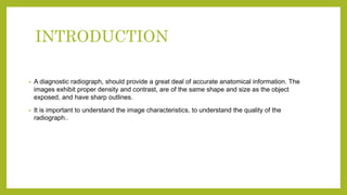
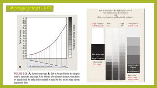
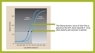
This document discusses various image characteristics that affect the quality of a radiograph. It defines key terms like radiopaque, radiolucent, and optical density. It explains how factors like kilovoltage, milliamperage, exposure time and distance affect radiographic density. The document also discusses contrast, speed, latitude and other characteristics. In summary, it provides a comprehensive overview of the technical factors that determine image quality and the diagnostic value of a radiograph.


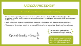
![RADIOGRAPHIC CONTRAST
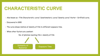
The difference in densities between light and dark regions on a radiograph
Only two densities
areas- black and white
are discernable
Due to low Kvp [<65
Kvp]
Many densities, in
different shades of
gray, is discernable.
Due to high Kvp [<70-
75]
High Contrast
Film/
Short scale
Contrast
Low Contrast
Film/
Long scale
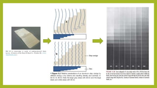
Contrast](https://image.slidesharecdn.com/imagecharacteristics-211029065349/85/Image-characteristics-14-320.jpg)
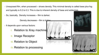
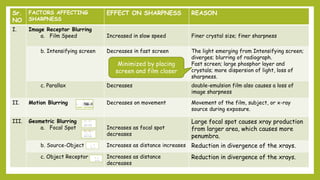
![Sr.
NO
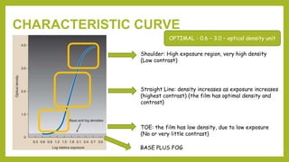
FACTORS AFFECTING CONTRAST EFFECT ON
CONTRAST
REASONS
I. Relation to Patient [ Subject Contrast]
a. Tissue Thickness Decreases with increases
subject thickness.
Depends upon different degree of
beam attenuation.
Increase in these factors -
more absorption of xray - less
remnant beam reaches film –
decreased density
b. Tissue Density Increased tissue density
decreases contrast
c. Atomic Number Increased atomic number,
increased contrast
Increases atomic number- higher
beam attenuation more contrast
variations
Eg. Cephalogram has high contrast
II. Relation to Xray Machine
a. Kvp
Low contrast with increased
Kvp
Less difference in attenuation
between the different parts of the
subject due to increased
penetrating power
b. Exposure rate Exposure rate – increase
brightness
Increased exposure time –
low contrast](https://image.slidesharecdn.com/imagecharacteristics-211029065349/85/Image-characteristics-15-320.jpg)
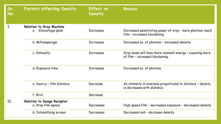
![Sr.
NO
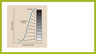
FACTORS AFFECTING CONTRAST EFFECT ON CONTRAST REASONS
I. Relation to Film [ Film Contrast]
a. Optical Density Low or High OD exhibit poor
contrast
Decreased/ Increased number of
non-diagnostic photons reaching
film
b. Film Speed Increased speed, low
contrast
c. Type of film Direct vs Indirect film Less contrast in indirect film
d. Emulsion Double emulsion – less
contrast
II. Relation to Processing
a. Scatter Radiation
Compton/ Coherent scatter
decreases contrast
Less difference in attenuation
between the different parts of the
subject due to increased
penetrating power
b. Fog Decreases contrast Developing of unexposed silver
halide crystals](https://image.slidesharecdn.com/imagecharacteristics-211029065349/85/Image-characteristics-16-320.jpg)
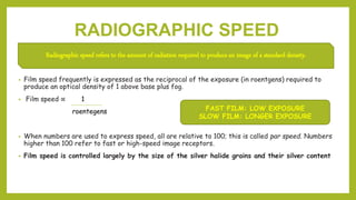

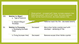
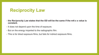
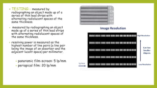
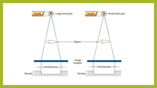
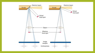
![SHARPNESS AND RESOLUTION
Resolution, or resolving power, is the ability of a radiograph to record separate structures that are close together.
Sr.NO FACTORS AFFECTING RESOLUTION EFFECT ON RESOLUTION
I. Type of Film
a. Direct exposure film Increases
b. Indirect exposure film Decreases [ 9 – 10 lp/mm]
II. Speed
a. Fast Film Decreases
b. Slow Film Increases](https://image.slidesharecdn.com/imagecharacteristics-211029065349/85/Image-characteristics-26-320.jpg)


![PERI-PROSTHETIC FRACTURE NAIL-PLATE CONSTRUCT [NPC].pptx](https://cdn.slidesharecdn.com/ss_thumbnails/drarunkumardrmohamedashrafperiprostheticfrasturenail-plateconstructnpc-260209164459-7e9d15a1-thumbnail.jpg?width=640&height=640&fit=bounds)
