SlideShare a Scribd company logo
Resistance Measurements & DC
bridges
Unit III: Voltmeter and ammeter methods, Wheatstone bridge, low
resistance measurements, low resistance measuring instruments
AC bridge theory, capacitance bridges, Inductance bridges, Q meter
4/4/2017 1
NEC 403 Unit I by Dr Naim R Kidwai,
Professor & Dean, JIT Jahangirabad
Voltmeter and Ammeter Methods
• Resistance can be measured using Ammeter and Voltmeter and
applying Ohm’s Law,
• Even with accurate instruments. errors has to be taken into account.
4/4/2017 2
NEC 403 Unit I by Dr Naim R Kidwai,
Professor & Dean, JIT Jahangirabad
RSupply
Voltage V
A
V
IV
I+IV
I
E
Voltmeter connected across load
• When Voltmeter is connected across
load then computer resistance R
=E/(I+IV)
• As actual value of R is E/I, presence of
voltmeter current IV introduces error
• Consequently calculated resistance is
less than actual.
Voltmeter and Ammeter Methods
When Voltmeter is connected across load, note ammeter reading,
then remove one terminal of voltmeter and again note ammeter
reading. If ammeter reading drops noticeably, then voltmeter current
is not much smaller than resistor current. In the case, voltmeter
should be connected across supply.
4/4/2017 3
NEC 403 Unit I by Dr Naim R Kidwai,
Professor & Dean, JIT Jahangirabad
• When Voltmeter is connected across
supply, then computer resistance
R =(E+EV)/I
• As actual value of R is E/I, presence of
voltage drop across voltmeter EA
introduces error.
• Consequently calculated resistance is
higher than actual.
RSupply
Voltage V
A
V
EA
I
E
Voltmeter connected across supply
+ -
Voltmeter and Ammeter Methods
Q. In order to measure resistance using voltmeter and ammeter,
Voltmeter is placed (a) across the load (b) across the supply. Supply
voltage is 10 V, Ammeter impedance is 10 , Voltmeter impedance is
1 M. Voltmeter and ammeter are assumed to be highly accurate,
precise and of high resolution.
What will be calculated resistance & % error in measurement for
setup (a) & (b) if Load resistance is (i) 10  (ii) 100  (iii) 1 K (iv) 10
K (v) 100 K (vi) 1 M (vii) 10 M
4/4/2017 4
NEC 403 Unit I by Dr Naim R Kidwai,
Professor & Dean, JIT Jahangirabad
In the problem, value of load resistance is given for which observed
value from setup (calculated resistance) and % error has to be
obtained.
The load resistance, voltmeter resistance and ammeter resistance can
be used to compute voltmeter and ammeter reading.
Voltmeter and Ammeter Methods
4/4/2017 5
NEC 403 Unit I by Dr Naim R Kidwai,
Professor & Dean, JIT Jahangirabad
RV IV
I+IV I
E
(a) Voltmeter connected across load
RV
RA
RV IV
I
E
(b)Voltmeter connected across supply
R
V
RA
EA
+ -
 
V
V
V
V
V
V
RR
RR
II
E
E
RR
RRE
II







.
eResistancCalculated
ReadingVoltmeter
.
.
readingAmmeter
A
A
A
A
RR
I
EE
R
RR
EEE
R
E
I








 


eResistancCalculated
.ReadingVoltmeter
readingAmmeter
Voltmeter and Ammeter Methods
4/4/2017 6
NEC 403 Unit I by Dr Naim R Kidwai,
Professor & Dean, JIT Jahangirabad
Load
Resistance
value R
(a) Voltmeter is connected across load (b)Voltmeter is connected across supply
Calculated Resistance
R।।Rv
% error in
measurement
Calculated Resistance
R + Ra
% error in
measurement
10  9.9999  -0.001 20  100
100  99.99  -0.01 110  10
1 K 0.999001 K -0.0999 1.01K 1
10 K 9.90099 K -0.9901 10.01 K 0.1
100 K 90.90909 K -9.0909 100.01 K 0.01
1 M 0.5 M -50 1.00001 M 0.001
10 M 0.9090909 M -90.9091 10.00001 M 0.0001
It can be noted that
connecting voltmeter across the load is suitable for low value resistance
measurements
connecting voltmeter across the supply is suitable for high value resistance
measurements
Wheatstone Bridge
• Accurate resistance measurement is done using Wheatstone bridge.
• When galvanometer deflects, the bridge is said to be unbalanced.
• Under balanced condition, null deflection is achieved.
• null deflection occurs when, potential across its terminals are equal
Under balanced condition
4/4/2017 7
NEC 403 Unit I by Dr Naim R Kidwai,
Professor & Dean, JIT Jahangirabad
R
V
Q
S
P
G
Precision
resistor
Precision
resistor
Unknown
resistor
Adjustable
Precision
resistor
I1
I2
S
R
Q
P
SIQIVV
RIPIVV
SQ
RP



eq.,twotheDividing
i.eand
i.e,
21
21
Q
P
SR or
Range of accurate measurement by Wheatstone bridge
is 5  -1012 
+
Wheatstone Bridge : Thevnin
Equivalent
4/4/2017 8
NEC 403 Unit I by Dr Naim R Kidwai,
Professor & Dean, JIT Jahangirabad
V
S
G
+ VR -
R
QP
r
+ VP -
+ VS -
+ VQ -
V
S
+ VR -
R
QP
+ VP -
+ VS -
+ VQ -
SR
QPG
-
Wheat stone bridge Circuit for VTH across galvanometer
Circuit for RTH across
galvanometer
G r
Thevnin equivalent
across galvanometer
SRQPRTh SQTh VVV 
SQ VV 
SRQP 
Wheatstone Bridge
Q. A wheat stone bridge has P=3.5 K, Q= 7 K and S=4 K at
balanced condition. Supply V= 10 V. The galvanometer has a current
sensitivity of 1 A/mm and internal resistance of 2.5 K . Calculate
the change in unknown resistance which can be detected by the
bridge.
4/4/2017 9
NEC 403 Unit I by Dr Naim R Kidwai,
Professor & Dean, JIT Jahangirabad
V
SR
R
VV
VArRIVVV
xx
SRQPR
AI
R
gThgSQTh
Th
g
33333.3
6
2
.10
m17.5K)5.267.3(1)(
K67.3K
42
42
75.3
75.3
1currentergalvanometdetectableMin.
k2k
7
5.3
.4
Q
P
SR













Wheatstone Bridge
4/4/2017 10
NEC 403 Unit I by Dr Naim R Kidwai,
Professor & Dean, JIT Jahangirabad










65.400465.0Thus
0047.2
665375.1
3385.3
A665375.1m
4
3385.310)(
V3385.300517.033333.3
Thusbydecreaseshall&increaseShall
,ergalvanometroughcurrent thdetectablemin.ofcaseIn
'
''
KR
KK
I
VV
RR
mA
S
VVV
II
VV
VVV
R
RR
RR
SR
RR
THRR
Low Resistance Measurements:
Four terminal resistance
• Connecting leads introduce error for low resistance measurement
• Error occurs due to voltage drop at contact where heavy current flow.
To avoid errors introduced by contacts, in very low resistances. two sets
of contact) are provided; current terminal & Potential terminal.
• Current terminals are outermost and handle large currents.
• Potential terminals are situated in between current terminals and
those handle current in A or mA
• Resistance is defined as between voltage terminals so voltage drop at
current terminal do not introduce error.
4/4/2017 11
NEC 403 Unit I by Dr Naim R Kidwai,
Professor & Dean, JIT Jahangirabad
potential terminals
Current terminals
Low Resistance Measurements:
Kelvin double bridge
• Modification of Wheatstone bridge For vey low resistance measurement
• It uses two additional resistances, to avoid effect of contact resistances
4/4/2017 12
NEC 403 Unit I by Dr Naim R Kidwai,
Professor & Dean, JIT Jahangirabad
V
I2
Q
S
P
G
Four terminal resistor
I1
+ VS -
R
A B
+ VR -
I3
I2-I3
Low Resistance Measurements:
Kelvin double bridge
4/4/2017 13
NEC 403 Unit I by Dr Naim R Kidwai,
Professor & Dean, JIT Jahangirabad
 
Q
P
SRPABAif
BII
AII
Q
PR
BII
I
Q
SBISIQIBIVV
AII
I
P
RAIRIPIAIVV
SQ
RP


















 

then
QBQP
Q
P
S
get,weeq.twotheDividing
Q
,and
P
conditionbalancedunder
31
31
31
2
3213
31
2
3213
Low Resistance Linear Ohmmeter
A constant current source is connected to the unknown resistance. The
voltage drop across resistance is amplified and measured through a
voltmeter. After calibration it giver resistance on a linear scale
4/4/2017 14
NEC 403 Unit I by Dr Naim R Kidwai,
Professor & Dean, JIT Jahangirabad
VRI Amplifier

More Related Content

What's hot

Q meter(rlc meter)
Q meter(rlc meter)Q meter(rlc meter)
Q meter(rlc meter)
najeebs10
 

What's hot (20)

Schering bridge
Schering bridge Schering bridge
Schering bridge
 
measurement of high voltage and high currents
 measurement of high voltage and high currents  measurement of high voltage and high currents
measurement of high voltage and high currents
 
Introduction To Electrical Engineering
Introduction To Electrical EngineeringIntroduction To Electrical Engineering
Introduction To Electrical Engineering
 
Electrical wiring system - and estimation
Electrical wiring system -  and estimation Electrical wiring system -  and estimation
Electrical wiring system - and estimation
 
DC potentiometers
DC potentiometersDC potentiometers
DC potentiometers
 
ESTIMATION & COSTING OF DOMESTIC & INDUSTRIAL WIRING
ESTIMATION & COSTING OF DOMESTIC & INDUSTRIAL WIRINGESTIMATION & COSTING OF DOMESTIC & INDUSTRIAL WIRING
ESTIMATION & COSTING OF DOMESTIC & INDUSTRIAL WIRING
 
Resistance Measurement instruments
Resistance Measurement instrumentsResistance Measurement instruments
Resistance Measurement instruments
 
Concept of Digital measurement, block Diagram & study of Voltmeter
Concept of Digital measurement, block Diagram & study of VoltmeterConcept of Digital measurement, block Diagram & study of Voltmeter
Concept of Digital measurement, block Diagram & study of Voltmeter
 
Bridge ppt 1
Bridge ppt 1Bridge ppt 1
Bridge ppt 1
 
Insulation Resistance Test
Insulation Resistance TestInsulation Resistance Test
Insulation Resistance Test
 
Hv module 3 Impulse voltage generation
Hv module 3 Impulse voltage generationHv module 3 Impulse voltage generation
Hv module 3 Impulse voltage generation
 
Electronic Measurement and Instrumentation
Electronic Measurement and InstrumentationElectronic Measurement and Instrumentation
Electronic Measurement and Instrumentation
 
EmI Unit-2.pptx
EmI Unit-2.pptxEmI Unit-2.pptx
EmI Unit-2.pptx
 
AC bridges: Inductance and Capacitance measurement
AC bridges: Inductance and Capacitance measurementAC bridges: Inductance and Capacitance measurement
AC bridges: Inductance and Capacitance measurement
 
The Kelvin Bridge
The Kelvin  BridgeThe Kelvin  Bridge
The Kelvin Bridge
 
Chapter 3 Generation of high voltages and current
Chapter 3 Generation of high voltages and currentChapter 3 Generation of high voltages and current
Chapter 3 Generation of high voltages and current
 
Q meter(rlc meter)
Q meter(rlc meter)Q meter(rlc meter)
Q meter(rlc meter)
 
Meter Forms: Wiring and Uses
Meter Forms: Wiring and UsesMeter Forms: Wiring and Uses
Meter Forms: Wiring and Uses
 
Introduction to CTs and PTs
Introduction to CTs and PTsIntroduction to CTs and PTs
Introduction to CTs and PTs
 
Fault finding method
Fault finding methodFault finding method
Fault finding method
 

Similar to Resistance measurement; DC bridges

REPORT -VALLUR THERMAL POWER PLANT
REPORT -VALLUR THERMAL POWER PLANTREPORT -VALLUR THERMAL POWER PLANT
REPORT -VALLUR THERMAL POWER PLANT
RAJPRASAD RS
 
DereMurray - APEC 2014 - Noise Susceptibility of delta-Vbe Temperature Sensors
DereMurray - APEC 2014 - Noise Susceptibility of delta-Vbe Temperature SensorsDereMurray - APEC 2014 - Noise Susceptibility of delta-Vbe Temperature Sensors
DereMurray - APEC 2014 - Noise Susceptibility of delta-Vbe Temperature Sensors
Derek Murray
 

Similar to Resistance measurement; DC bridges (20)

Chapter2
Chapter2Chapter2
Chapter2
 
Chapter2
Chapter2Chapter2
Chapter2
 
eem-2020309.pdf
eem-2020309.pdfeem-2020309.pdf
eem-2020309.pdf
 
Measurement of resistance
Measurement of resistanceMeasurement of resistance
Measurement of resistance
 
EMI Unit 5 Bridges and Measurement of Physical Parameters
EMI Unit 5 Bridges and  Measurement of Physical ParametersEMI Unit 5 Bridges and  Measurement of Physical Parameters
EMI Unit 5 Bridges and Measurement of Physical Parameters
 
PMMC instruments, Galvanometer, DC Voltmeter, DC Ammeter
PMMC instruments, Galvanometer, DC Voltmeter, DC AmmeterPMMC instruments, Galvanometer, DC Voltmeter, DC Ammeter
PMMC instruments, Galvanometer, DC Voltmeter, DC Ammeter
 
AC and DC BridgePPT for engineering students
AC and DC BridgePPT for engineering studentsAC and DC BridgePPT for engineering students
AC and DC BridgePPT for engineering students
 
REPORT -VALLUR THERMAL POWER PLANT
REPORT -VALLUR THERMAL POWER PLANTREPORT -VALLUR THERMAL POWER PLANT
REPORT -VALLUR THERMAL POWER PLANT
 
unit-iii- Sphere Gap.ppt
unit-iii- Sphere Gap.pptunit-iii- Sphere Gap.ppt
unit-iii- Sphere Gap.ppt
 
DereMurray - APEC 2014 - Noise Susceptibility of delta-Vbe Temperature Sensors
DereMurray - APEC 2014 - Noise Susceptibility of delta-Vbe Temperature SensorsDereMurray - APEC 2014 - Noise Susceptibility of delta-Vbe Temperature Sensors
DereMurray - APEC 2014 - Noise Susceptibility of delta-Vbe Temperature Sensors
 
Measurement of Resistance
Measurement of ResistanceMeasurement of Resistance
Measurement of Resistance
 
Distribution Transformer testing, West Bengal, India
Distribution Transformer testing,  West Bengal, IndiaDistribution Transformer testing,  West Bengal, India
Distribution Transformer testing, West Bengal, India
 
Ac voltage
Ac voltageAc voltage
Ac voltage
 
Ac voltage
Ac voltageAc voltage
Ac voltage
 
Dc voltage
Dc voltageDc voltage
Dc voltage
 
Unit 3
Unit 3Unit 3
Unit 3
 
Q meter ppt
Q meter pptQ meter ppt
Q meter ppt
 
Unit 1-2-b
Unit 1-2-bUnit 1-2-b
Unit 1-2-b
 
Rec101 unit iv emi
Rec101 unit iv emiRec101 unit iv emi
Rec101 unit iv emi
 
Comparision methods of measurements
Comparision methods of measurementsComparision methods of measurements
Comparision methods of measurements
 

More from Dr Naim R Kidwai

More from Dr Naim R Kidwai (20)

Asynchronous sequential circuit analysis
Asynchronous sequential circuit analysisAsynchronous sequential circuit analysis
Asynchronous sequential circuit analysis
 
synchronous Sequential circuit counters and registers
synchronous Sequential circuit counters and registerssynchronous Sequential circuit counters and registers
synchronous Sequential circuit counters and registers
 
Clocked Sequential circuit analysis and design
Clocked Sequential circuit analysis and designClocked Sequential circuit analysis and design
Clocked Sequential circuit analysis and design
 
Sequential circuit-flip flops
Sequential circuit-flip flopsSequential circuit-flip flops
Sequential circuit-flip flops
 
Sampling Theorem
Sampling TheoremSampling Theorem
Sampling Theorem
 
Moodle introduction
Moodle introductionMoodle introduction
Moodle introduction
 
Project financial feasibility
Project financial feasibilityProject financial feasibility
Project financial feasibility
 
financing infrastructure projects
financing infrastructure projectsfinancing infrastructure projects
financing infrastructure projects
 
financing projects
financing projectsfinancing projects
financing projects
 
multiple projects and constraints
multiple projects and constraintsmultiple projects and constraints
multiple projects and constraints
 
project risk analysis
project risk analysisproject risk analysis
project risk analysis
 
Nec 602 unit ii Random Variables and Random process
Nec 602 unit ii Random Variables and Random processNec 602 unit ii Random Variables and Random process
Nec 602 unit ii Random Variables and Random process
 
spread spectrum communication
spread spectrum communicationspread spectrum communication
spread spectrum communication
 
Error Control coding
Error Control codingError Control coding
Error Control coding
 
information theory
information theoryinformation theory
information theory
 
Rec101 unit ii (part 2) bjt biasing and re model
Rec101 unit ii (part 2) bjt biasing and re modelRec101 unit ii (part 2) bjt biasing and re model
Rec101 unit ii (part 2) bjt biasing and re model
 
Rec101 unit ii (part 3) field effect transistor
Rec101 unit ii (part 3) field effect transistorRec101 unit ii (part 3) field effect transistor
Rec101 unit ii (part 3) field effect transistor
 
Rec101 unit ii (part 1) bjt characteristics
Rec101 unit ii (part 1) bjt characteristicsRec101 unit ii (part 1) bjt characteristics
Rec101 unit ii (part 1) bjt characteristics
 
Rec101 unit v communication engg
Rec101 unit v communication enggRec101 unit v communication engg
Rec101 unit v communication engg
 
Rec101 unit iii operational amplifier
Rec101 unit iii operational amplifierRec101 unit iii operational amplifier
Rec101 unit iii operational amplifier
 

Recently uploaded

Standard Reomte Control Interface - Neometrix
Standard Reomte Control Interface - NeometrixStandard Reomte Control Interface - Neometrix
Standard Reomte Control Interface - Neometrix
Neometrix_Engineering_Pvt_Ltd
 
Fruit shop management system project report.pdf
Fruit shop management system project report.pdfFruit shop management system project report.pdf
Fruit shop management system project report.pdf
Kamal Acharya
 

Recently uploaded (20)

KIT-601 Lecture Notes-UNIT-5.pdf Frame Works and Visualization
KIT-601 Lecture Notes-UNIT-5.pdf Frame Works and VisualizationKIT-601 Lecture Notes-UNIT-5.pdf Frame Works and Visualization
KIT-601 Lecture Notes-UNIT-5.pdf Frame Works and Visualization
 
Architectural Portfolio Sean Lockwood
Architectural Portfolio Sean LockwoodArchitectural Portfolio Sean Lockwood
Architectural Portfolio Sean Lockwood
 
Cloud-Computing_CSE311_Computer-Networking CSE GUB BD - Shahidul.pptx
Cloud-Computing_CSE311_Computer-Networking CSE GUB BD - Shahidul.pptxCloud-Computing_CSE311_Computer-Networking CSE GUB BD - Shahidul.pptx
Cloud-Computing_CSE311_Computer-Networking CSE GUB BD - Shahidul.pptx
 
Natalia Rutkowska - BIM School Course in Kraków
Natalia Rutkowska - BIM School Course in KrakówNatalia Rutkowska - BIM School Course in Kraków
Natalia Rutkowska - BIM School Course in Kraków
 
NO1 Pandit Amil Baba In Bahawalpur, Sargodha, Sialkot, Sheikhupura, Rahim Yar...
NO1 Pandit Amil Baba In Bahawalpur, Sargodha, Sialkot, Sheikhupura, Rahim Yar...NO1 Pandit Amil Baba In Bahawalpur, Sargodha, Sialkot, Sheikhupura, Rahim Yar...
NO1 Pandit Amil Baba In Bahawalpur, Sargodha, Sialkot, Sheikhupura, Rahim Yar...
 
ASME IX(9) 2007 Full Version .pdf
ASME IX(9)  2007 Full Version       .pdfASME IX(9)  2007 Full Version       .pdf
ASME IX(9) 2007 Full Version .pdf
 
Arduino based vehicle speed tracker project
Arduino based vehicle speed tracker projectArduino based vehicle speed tracker project
Arduino based vehicle speed tracker project
 
Furniture showroom management system project.pdf
Furniture showroom management system project.pdfFurniture showroom management system project.pdf
Furniture showroom management system project.pdf
 
Introduction to Machine Learning Unit-4 Notes for II-II Mechanical Engineering
Introduction to Machine Learning Unit-4 Notes for II-II Mechanical EngineeringIntroduction to Machine Learning Unit-4 Notes for II-II Mechanical Engineering
Introduction to Machine Learning Unit-4 Notes for II-II Mechanical Engineering
 
Standard Reomte Control Interface - Neometrix
Standard Reomte Control Interface - NeometrixStandard Reomte Control Interface - Neometrix
Standard Reomte Control Interface - Neometrix
 
KIT-601 Lecture Notes-UNIT-4.pdf Frequent Itemsets and Clustering
KIT-601 Lecture Notes-UNIT-4.pdf Frequent Itemsets and ClusteringKIT-601 Lecture Notes-UNIT-4.pdf Frequent Itemsets and Clustering
KIT-601 Lecture Notes-UNIT-4.pdf Frequent Itemsets and Clustering
 
ENERGY STORAGE DEVICES INTRODUCTION UNIT-I
ENERGY STORAGE DEVICES  INTRODUCTION UNIT-IENERGY STORAGE DEVICES  INTRODUCTION UNIT-I
ENERGY STORAGE DEVICES INTRODUCTION UNIT-I
 
fluid mechanics gate notes . gate all pyqs answer
fluid mechanics gate notes . gate all pyqs answerfluid mechanics gate notes . gate all pyqs answer
fluid mechanics gate notes . gate all pyqs answer
 
Halogenation process of chemical process industries
Halogenation process of chemical process industriesHalogenation process of chemical process industries
Halogenation process of chemical process industries
 
The Ultimate Guide to External Floating Roofs for Oil Storage Tanks.docx
The Ultimate Guide to External Floating Roofs for Oil Storage Tanks.docxThe Ultimate Guide to External Floating Roofs for Oil Storage Tanks.docx
The Ultimate Guide to External Floating Roofs for Oil Storage Tanks.docx
 
HYDROPOWER - Hydroelectric power generation
HYDROPOWER - Hydroelectric power generationHYDROPOWER - Hydroelectric power generation
HYDROPOWER - Hydroelectric power generation
 
Introduction to Machine Learning Unit-5 Notes for II-II Mechanical Engineering
Introduction to Machine Learning Unit-5 Notes for II-II Mechanical EngineeringIntroduction to Machine Learning Unit-5 Notes for II-II Mechanical Engineering
Introduction to Machine Learning Unit-5 Notes for II-II Mechanical Engineering
 
A CASE STUDY ON ONLINE TICKET BOOKING SYSTEM PROJECT.pdf
A CASE STUDY ON ONLINE TICKET BOOKING SYSTEM PROJECT.pdfA CASE STUDY ON ONLINE TICKET BOOKING SYSTEM PROJECT.pdf
A CASE STUDY ON ONLINE TICKET BOOKING SYSTEM PROJECT.pdf
 
Peek implant persentation - Copy (1).pdf
Peek implant persentation - Copy (1).pdfPeek implant persentation - Copy (1).pdf
Peek implant persentation - Copy (1).pdf
 
Fruit shop management system project report.pdf
Fruit shop management system project report.pdfFruit shop management system project report.pdf
Fruit shop management system project report.pdf
 

Resistance measurement; DC bridges

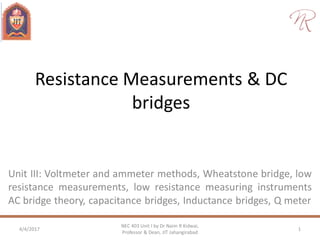
  • 1. Resistance Measurements & DC bridges Unit III: Voltmeter and ammeter methods, Wheatstone bridge, low resistance measurements, low resistance measuring instruments AC bridge theory, capacitance bridges, Inductance bridges, Q meter 4/4/2017 1 NEC 403 Unit I by Dr Naim R Kidwai, Professor & Dean, JIT Jahangirabad
  • 2. Voltmeter and Ammeter Methods • Resistance can be measured using Ammeter and Voltmeter and applying Ohm’s Law, • Even with accurate instruments. errors has to be taken into account. 4/4/2017 2 NEC 403 Unit I by Dr Naim R Kidwai, Professor & Dean, JIT Jahangirabad RSupply Voltage V A V IV I+IV I E Voltmeter connected across load • When Voltmeter is connected across load then computer resistance R =E/(I+IV) • As actual value of R is E/I, presence of voltmeter current IV introduces error • Consequently calculated resistance is less than actual.
  • 3. Voltmeter and Ammeter Methods When Voltmeter is connected across load, note ammeter reading, then remove one terminal of voltmeter and again note ammeter reading. If ammeter reading drops noticeably, then voltmeter current is not much smaller than resistor current. In the case, voltmeter should be connected across supply. 4/4/2017 3 NEC 403 Unit I by Dr Naim R Kidwai, Professor & Dean, JIT Jahangirabad • When Voltmeter is connected across supply, then computer resistance R =(E+EV)/I • As actual value of R is E/I, presence of voltage drop across voltmeter EA introduces error. • Consequently calculated resistance is higher than actual. RSupply Voltage V A V EA I E Voltmeter connected across supply + -
  • 4. Voltmeter and Ammeter Methods Q. In order to measure resistance using voltmeter and ammeter, Voltmeter is placed (a) across the load (b) across the supply. Supply voltage is 10 V, Ammeter impedance is 10 , Voltmeter impedance is 1 M. Voltmeter and ammeter are assumed to be highly accurate, precise and of high resolution. What will be calculated resistance & % error in measurement for setup (a) & (b) if Load resistance is (i) 10  (ii) 100  (iii) 1 K (iv) 10 K (v) 100 K (vi) 1 M (vii) 10 M 4/4/2017 4 NEC 403 Unit I by Dr Naim R Kidwai, Professor & Dean, JIT Jahangirabad In the problem, value of load resistance is given for which observed value from setup (calculated resistance) and % error has to be obtained. The load resistance, voltmeter resistance and ammeter resistance can be used to compute voltmeter and ammeter reading.
  • 5. Voltmeter and Ammeter Methods 4/4/2017 5 NEC 403 Unit I by Dr Naim R Kidwai, Professor & Dean, JIT Jahangirabad RV IV I+IV I E (a) Voltmeter connected across load RV RA RV IV I E (b)Voltmeter connected across supply R V RA EA + -   V V V V V V RR RR II E E RR RRE II        . eResistancCalculated ReadingVoltmeter . . readingAmmeter A A A A RR I EE R RR EEE R E I             eResistancCalculated .ReadingVoltmeter readingAmmeter
  • 6. Voltmeter and Ammeter Methods 4/4/2017 6 NEC 403 Unit I by Dr Naim R Kidwai, Professor & Dean, JIT Jahangirabad Load Resistance value R (a) Voltmeter is connected across load (b)Voltmeter is connected across supply Calculated Resistance R।।Rv % error in measurement Calculated Resistance R + Ra % error in measurement 10  9.9999  -0.001 20  100 100  99.99  -0.01 110  10 1 K 0.999001 K -0.0999 1.01K 1 10 K 9.90099 K -0.9901 10.01 K 0.1 100 K 90.90909 K -9.0909 100.01 K 0.01 1 M 0.5 M -50 1.00001 M 0.001 10 M 0.9090909 M -90.9091 10.00001 M 0.0001 It can be noted that connecting voltmeter across the load is suitable for low value resistance measurements connecting voltmeter across the supply is suitable for high value resistance measurements
  • 7. Wheatstone Bridge • Accurate resistance measurement is done using Wheatstone bridge. • When galvanometer deflects, the bridge is said to be unbalanced. • Under balanced condition, null deflection is achieved. • null deflection occurs when, potential across its terminals are equal Under balanced condition 4/4/2017 7 NEC 403 Unit I by Dr Naim R Kidwai, Professor & Dean, JIT Jahangirabad R V Q S P G Precision resistor Precision resistor Unknown resistor Adjustable Precision resistor I1 I2 S R Q P SIQIVV RIPIVV SQ RP    eq.,twotheDividing i.eand i.e, 21 21 Q P SR or Range of accurate measurement by Wheatstone bridge is 5  -1012 
  • 8. + Wheatstone Bridge : Thevnin Equivalent 4/4/2017 8 NEC 403 Unit I by Dr Naim R Kidwai, Professor & Dean, JIT Jahangirabad V S G + VR - R QP r + VP - + VS - + VQ - V S + VR - R QP + VP - + VS - + VQ - SR QPG - Wheat stone bridge Circuit for VTH across galvanometer Circuit for RTH across galvanometer G r Thevnin equivalent across galvanometer SRQPRTh SQTh VVV  SQ VV  SRQP 
  • 9. Wheatstone Bridge Q. A wheat stone bridge has P=3.5 K, Q= 7 K and S=4 K at balanced condition. Supply V= 10 V. The galvanometer has a current sensitivity of 1 A/mm and internal resistance of 2.5 K . Calculate the change in unknown resistance which can be detected by the bridge. 4/4/2017 9 NEC 403 Unit I by Dr Naim R Kidwai, Professor & Dean, JIT Jahangirabad V SR R VV VArRIVVV xx SRQPR AI R gThgSQTh Th g 33333.3 6 2 .10 m17.5K)5.267.3(1)( K67.3K 42 42 75.3 75.3 1currentergalvanometdetectableMin. k2k 7 5.3 .4 Q P SR             
  • 10. Wheatstone Bridge 4/4/2017 10 NEC 403 Unit I by Dr Naim R Kidwai, Professor & Dean, JIT Jahangirabad           65.400465.0Thus 0047.2 665375.1 3385.3 A665375.1m 4 3385.310)( V3385.300517.033333.3 Thusbydecreaseshall&increaseShall ,ergalvanometroughcurrent thdetectablemin.ofcaseIn ' '' KR KK I VV RR mA S VVV II VV VVV R RR RR SR RR THRR
  • 11. Low Resistance Measurements: Four terminal resistance • Connecting leads introduce error for low resistance measurement • Error occurs due to voltage drop at contact where heavy current flow. To avoid errors introduced by contacts, in very low resistances. two sets of contact) are provided; current terminal & Potential terminal. • Current terminals are outermost and handle large currents. • Potential terminals are situated in between current terminals and those handle current in A or mA • Resistance is defined as between voltage terminals so voltage drop at current terminal do not introduce error. 4/4/2017 11 NEC 403 Unit I by Dr Naim R Kidwai, Professor & Dean, JIT Jahangirabad potential terminals Current terminals
  • 12. Low Resistance Measurements: Kelvin double bridge • Modification of Wheatstone bridge For vey low resistance measurement • It uses two additional resistances, to avoid effect of contact resistances 4/4/2017 12 NEC 403 Unit I by Dr Naim R Kidwai, Professor & Dean, JIT Jahangirabad V I2 Q S P G Four terminal resistor I1 + VS - R A B + VR - I3 I2-I3
  • 13. Low Resistance Measurements: Kelvin double bridge 4/4/2017 13 NEC 403 Unit I by Dr Naim R Kidwai, Professor & Dean, JIT Jahangirabad   Q P SRPABAif BII AII Q PR BII I Q SBISIQIBIVV AII I P RAIRIPIAIVV SQ RP                      then QBQP Q P S get,weeq.twotheDividing Q ,and P conditionbalancedunder 31 31 31 2 3213 31 2 3213
  • 14. Low Resistance Linear Ohmmeter A constant current source is connected to the unknown resistance. The voltage drop across resistance is amplified and measured through a voltmeter. After calibration it giver resistance on a linear scale 4/4/2017 14 NEC 403 Unit I by Dr Naim R Kidwai, Professor & Dean, JIT Jahangirabad VRI Amplifier