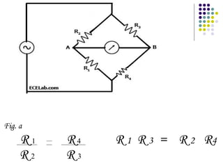
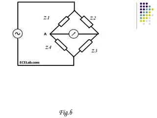
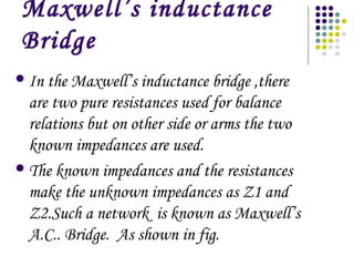
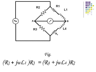
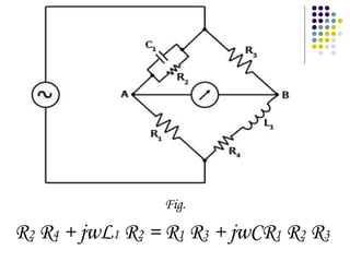
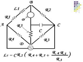
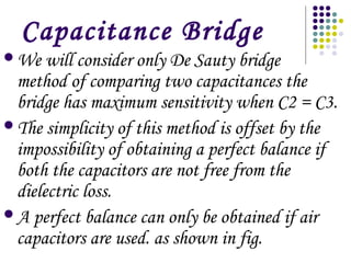
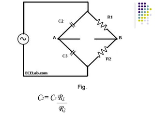
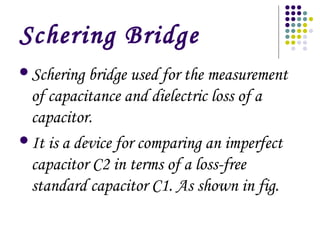
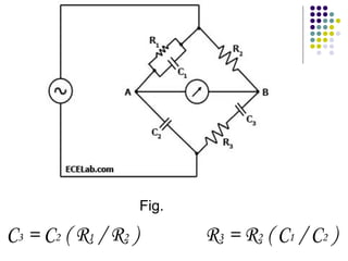
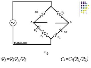
A.C.Bridges
A.C.Bridges are those circuits which are
used to measured the unknown resistances,
capacitance ,inductance ,frequency and
mutual inductance.
Wheat Stone Bridge
Resistances can be measured by direct-
current ,as shown in fig. a
Fig. a
R 1 R4 R 1 R 3 = R 2 R4
R 2 R 3
Inductance and capacitance can also
be measured by a similar four-arm
bridge, as shown in fig.b.
In this case the alternating current
source is employed by a vibration
galvanometer.
Fig.b
Maxwell’s inductance
Bridge
In the Maxwell’s inductance bridge ,there
are two pure resistances used for balance
relations but on other side or arms the two
known impedances are used.
The known impedances and the resistances
make the unknown impedances as Z1 and
Z2.Such a network is known as Maxwell’s
A.C.. Bridge. As shown in fig.
Fig.
(R1 + jwL1 )R3 = (R4 + jwL4 )R2
Maxwell’s Wien
Bridge
In the Maxwell’s Wien Bridge the positive
phase angle of the inductance may be
compensated by the negative phase angle
of the capacitance impedance put in the
opposite arm.
The unknown inductance then becomes
known in terms of the capacitance. As
shown in fig.
Fig.
R2 R4 + jwL1 R2 = R1 R3 + jwCR1 R2 R3
Anderson Bridge
In the Anderson Bridge the unknown
inductance is measured in terms of a known
capacitance and resistance.
this method is capable of precise measurements
of inductance over a wide range of values from
a few micro-henrys to several henrys and is the
best bridge method.
Capacitance Bridge
We will consider only De Sauty bridge
method of comparing two capacitances the
bridge has maximum sensitivity when C2 = C3.
The simplicity of this method is offset by the
impossibility of obtaining a perfect balance if
both the capacitors are not free from the
dielectric loss.
A perfect balance can only be obtained if air
capacitors are used. as shown in fig.
Fig.
C2= C3 R1
R2
Schering Bridge
Schering bridge used for the measurement
of capacitance and dielectric loss of a
capacitor.
It is a device for comparing an imperfect
capacitor C2 in terms of a loss-free
standard capacitor C1. As shown in fig.
Fig.
C3 = C2 ( R1 / R2 ) R3 = R2 ( C1 / C2 )
Wien Series Bridge
It is a simple ratio bridge and is used for
audio-frequency measurement of
capacitance over a wide range. As shown
in fig.
Fig.
R1=R2R4/R3 C1=C4(R3/R2)
Wien Parallel Bridge
It is also a ratio bridge used mainly as the
feedback network in the wide range audio-
frequency R-C oscillators.
It is may be used for the measurement of
the audio-frequency but it is not as
accurate as the modern digital frequency
meters. As shown in fig.
Fig.
C2 = R2 = R3
C1 R1 R4

Ac bridge

  • 1.
  • 2.
    A.C.Bridges are thosecircuits which are used to measured the unknown resistances, capacitance ,inductance ,frequency and mutual inductance.
  • 3.
    Wheat Stone Bridge Resistancescan be measured by direct- current ,as shown in fig. a
  • 4.
    Fig. a R 1R4 R 1 R 3 = R 2 R4 R 2 R 3
  • 5.
    Inductance and capacitancecan also be measured by a similar four-arm bridge, as shown in fig.b. In this case the alternating current source is employed by a vibration galvanometer.
  • 6.
  • 7.
    Maxwell’s inductance Bridge In theMaxwell’s inductance bridge ,there are two pure resistances used for balance relations but on other side or arms the two known impedances are used. The known impedances and the resistances make the unknown impedances as Z1 and Z2.Such a network is known as Maxwell’s A.C.. Bridge. As shown in fig.
  • 8.
    Fig. (R1 + jwL1)R3 = (R4 + jwL4 )R2
  • 9.
    Maxwell’s Wien Bridge In theMaxwell’s Wien Bridge the positive phase angle of the inductance may be compensated by the negative phase angle of the capacitance impedance put in the opposite arm. The unknown inductance then becomes known in terms of the capacitance. As shown in fig.
  • 10.
    Fig. R2 R4 +jwL1 R2 = R1 R3 + jwCR1 R2 R3
  • 11.
    Anderson Bridge In theAnderson Bridge the unknown inductance is measured in terms of a known capacitance and resistance. this method is capable of precise measurements of inductance over a wide range of values from a few micro-henrys to several henrys and is the best bridge method.
  • 13.
    Capacitance Bridge We willconsider only De Sauty bridge method of comparing two capacitances the bridge has maximum sensitivity when C2 = C3. The simplicity of this method is offset by the impossibility of obtaining a perfect balance if both the capacitors are not free from the dielectric loss. A perfect balance can only be obtained if air capacitors are used. as shown in fig.
  • 14.
  • 15.
    Schering Bridge Schering bridgeused for the measurement of capacitance and dielectric loss of a capacitor. It is a device for comparing an imperfect capacitor C2 in terms of a loss-free standard capacitor C1. As shown in fig.
  • 16.
    Fig. C3 = C2( R1 / R2 ) R3 = R2 ( C1 / C2 )
  • 17.
    Wien Series Bridge Itis a simple ratio bridge and is used for audio-frequency measurement of capacitance over a wide range. As shown in fig.
  • 18.
  • 19.
    Wien Parallel Bridge Itis also a ratio bridge used mainly as the feedback network in the wide range audio- frequency R-C oscillators. It is may be used for the measurement of the audio-frequency but it is not as accurate as the modern digital frequency meters. As shown in fig.
  • 20.
    Fig. C2 = R2= R3 C1 R1 R4