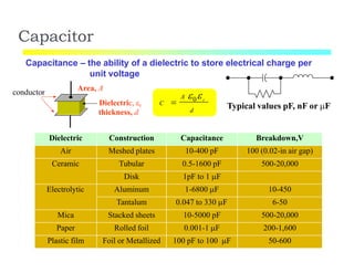
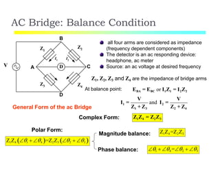
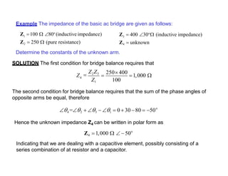
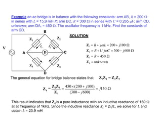
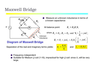
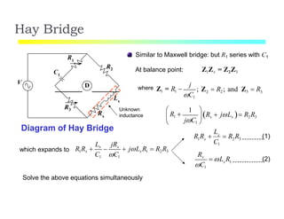
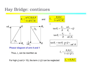
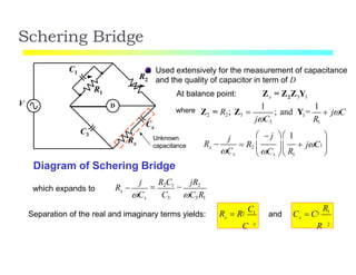
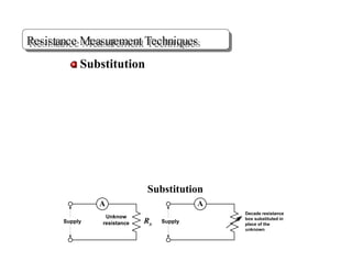
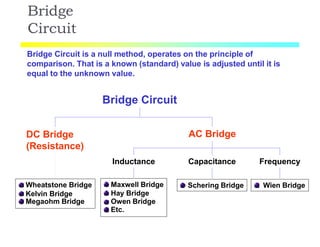
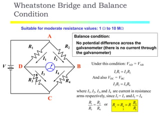
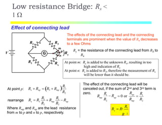
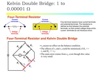
The document discusses various resistance measurement techniques including the Wheatstone bridge, Kelvin bridge, and AC bridges. The Wheatstone bridge is based on balancing two voltage ratios and can measure resistances from 1 ohm to 10 megohms. The Kelvin bridge is a more precise version that eliminates errors from lead resistance and can measure down to 0.00001 ohms. AC bridges can measure impedances that include resistance, inductance, and capacitance components.
Here we study the construction of hay's bridge, hay's bridge theory with expression, and example, hay's bridge phasor diagram. The Hay’s bridge is used for determining the self-inductance of the circuit. The bridge is the advanced form of Maxwell’s bridge.
The devise that is used for measurement of certain physical quantity is called as measuring instrument. This article discusses what the measuring instruments are, their types, functions of the measuring instruments and advantages and disadvantages of the analogue and digital ...
Digital Voltmeter, Digital Ammeter and Digital MultimeterPraveen Kumar
This ppt deals with Digital meters,the digital components used in them,principle behind the working of Digital Voltmeter(DC) Digital Voltmeter(AC) and mechanism of Measurement of Current and Measurement of Resistance. Finally A complete DMM also the Measurement of hfe. A small project on constructing digital voltmeter and ohmmeter using Arduino.
Ohm's Law V = I x R (Volts = Current x Resistance). The Ohm (Ω) is a unit of electrical resistance equal to that of a conductor in which a current of one ampere is produced by a potential of one volt across its terminals. 1)Measurement of Low resistance: 1) Ammeter Voltmeter method: This is very popular method for measurement of medium resistances since ...
The transducer whose resistance varies because of the environmental effects such type of transducer is known as the resistive transducer. The change in resistance is measured by the ac or dc measuring devices. The resistive transducer is used for measuring the physical quantities like temperature, displacement, vibration etc.
The measurement of the physical quantity is quite difficult. The resistive transducer converts the physical quantities into variable resistance which is easily measured by the meters. The process of variation in resistance is widely used in the industrial applications.
The resistive transducer can work both as the primary as well as the secondary transducer. The primary transducer changes the physical quantities into a mechanical signal, and secondary transducer directly transforms it into an electrical signal.
Working Principle of Resistive Transducer
The resistive transducer element works on the principle that the resistance of the element is directly proportional to the length of the conductor and inversely proportional to the area of the conductor. equation-1
Where R – resistance in ohms.
A – cross-section area of the conductor in meter square.
L – Length of the conductor in meter square.
ρ – the resistivity of the conductor in materials in ohm meter.
The resistive transducer is designed by considering the variation of the length, area and resistivity of the metal.
Applications of Resistive Transducer
The following are the applications of the resistive transducer.
Potentiometer – The translation and rotatory potentiometer are the examples of the resistive transducers. The resistance of their conductor varies with the variation in their lengths which is used for the measurement of displacement.
Strain gauges – The resistance of their semiconductor material changes when the strain occurs on it. This property of metals is used for the measurement of the pressure, force-displacement etc.
Resistance Thermometer – The resistance of the metals changes because of changes in temperature. This property of conductor is used for measuring the temperature.
Thermistor – It works on the principle that the temperature coefficient of the thermistor material varies with the temperature. The thermistor has the negative temperature coefficient. The Negative temperature coefficient means the temperature is inversely proportional to resistance.
Power measurement is a valid technique to measure that how much the power is being transmitted through the entire system.
In this presentation you will estimate and understand the following objectives
Wattmeter as a device
Power measurement techniques
Classical based history
Construction of wattmeter
Working of Wattmeter
Power measurement of direct and indirect way
Power measurement in three phase applications
Applications of Wattmeter
Overview of the fundamental roles in Hydropower generation and the components involved in wider Electrical Engineering.
This paper presents the design and construction of hydroelectric dams from the hydrologist’s survey of the valley before construction, all aspects and involved disciplines, fluid dynamics, structural engineering, generation and mains frequency regulation to the very transmission of power through the network in the United Kingdom.
Author: Robbie Edward Sayers
Collaborators and co editors: Charlie Sims and Connor Healey.
(C) 2024 Robbie E. Sayers
Quality defects in TMT Bars, Possible causes and Potential Solutions.PrashantGoswami42
Maintaining high-quality standards in the production of TMT bars is crucial for ensuring structural integrity in construction. Addressing common defects through careful monitoring, standardized processes, and advanced technology can significantly improve the quality of TMT bars. Continuous training and adherence to quality control measures will also play a pivotal role in minimizing these defects.
Industrial Training at Shahjalal Fertilizer Company Limited (SFCL)MdTanvirMahtab2
This presentation is about the working procedure of Shahjalal Fertilizer Company Limited (SFCL). A Govt. owned Company of Bangladesh Chemical Industries Corporation under Ministry of Industries.
Sachpazis:Terzaghi Bearing Capacity Estimation in simple terms with Calculati...Dr.Costas Sachpazis
Terzaghi's soil bearing capacity theory, developed by Karl Terzaghi, is a fundamental principle in geotechnical engineering used to determine the bearing capacity of shallow foundations. This theory provides a method to calculate the ultimate bearing capacity of soil, which is the maximum load per unit area that the soil can support without undergoing shear failure. The Calculation HTML Code included.
Student information management system project report ii.pdfKamal Acharya
Our project explains about the student management. This project mainly explains the various actions related to student details. This project shows some ease in adding, editing and deleting the student details. It also provides a less time consuming process for viewing, adding, editing and deleting the marks of the students.
Final project report on grocery store management system..pdfKamal Acharya
In today’s fast-changing business environment, it’s extremely important to be able to respond to client needs in the most effective and timely manner. If your customers wish to see your business online and have instant access to your products or services.
Online Grocery Store is an e-commerce website, which retails various grocery products. This project allows viewing various products available enables registered users to purchase desired products instantly using Paytm, UPI payment processor (Instant Pay) and also can place order by using Cash on Delivery (Pay Later) option. This project provides an easy access to Administrators and Managers to view orders placed using Pay Later and Instant Pay options.
In order to develop an e-commerce website, a number of Technologies must be studied and understood. These include multi-tiered architecture, server and client-side scripting techniques, implementation technologies, programming language (such as PHP, HTML, CSS, JavaScript) and MySQL relational databases. This is a project with the objective to develop a basic website where a consumer is provided with a shopping cart website and also to know about the technologies used to develop such a website.
This document will discuss each of the underlying technologies to create and implement an e- commerce website.
Hybrid optimization of pumped hydro system and solar- Engr. Abdul-Azeez.pdffxintegritypublishin
Advancements in technology unveil a myriad of electrical and electronic breakthroughs geared towards efficiently harnessing limited resources to meet human energy demands. The optimization of hybrid solar PV panels and pumped hydro energy supply systems plays a pivotal role in utilizing natural resources effectively. This initiative not only benefits humanity but also fosters environmental sustainability. The study investigated the design optimization of these hybrid systems, focusing on understanding solar radiation patterns, identifying geographical influences on solar radiation, formulating a mathematical model for system optimization, and determining the optimal configuration of PV panels and pumped hydro storage. Through a comparative analysis approach and eight weeks of data collection, the study addressed key research questions related to solar radiation patterns and optimal system design. The findings highlighted regions with heightened solar radiation levels, showcasing substantial potential for power generation and emphasizing the system's efficiency. Optimizing system design significantly boosted power generation, promoted renewable energy utilization, and enhanced energy storage capacity. The study underscored the benefits of optimizing hybrid solar PV panels and pumped hydro energy supply systems for sustainable energy usage. Optimizing the design of solar PV panels and pumped hydro energy supply systems as examined across diverse climatic conditions in a developing country, not only enhances power generation but also improves the integration of renewable energy sources and boosts energy storage capacities, particularly beneficial for less economically prosperous regions. Additionally, the study provides valuable insights for advancing energy research in economically viable areas. Recommendations included conducting site-specific assessments, utilizing advanced modeling tools, implementing regular maintenance protocols, and enhancing communication among system components.
Cosmetic shop management system project report.pdfKamal Acharya
Buying new cosmetic products is difficult. It can even be scary for those who have sensitive skin and are prone to skin trouble. The information needed to alleviate this problem is on the back of each product, but it's thought to interpret those ingredient lists unless you have a background in chemistry.
Instead of buying and hoping for the best, we can use data science to help us predict which products may be good fits for us. It includes various function programs to do the above mentioned tasks.
Data file handling has been effectively used in the program.
The automated cosmetic shop management system should deal with the automation of general workflow and administration process of the shop. The main processes of the system focus on customer's request where the system is able to search the most appropriate products and deliver it to the customers. It should help the employees to quickly identify the list of cosmetic product that have reached the minimum quantity and also keep a track of expired date for each cosmetic product. It should help the employees to find the rack number in which the product is placed.It is also Faster and more efficient way.
NO1 Uk best vashikaran specialist in delhi vashikaran baba near me online vas...Amil Baba Dawood bangali
Contact with Dawood Bhai Just call on +92322-6382012 and we'll help you. We'll solve all your problems within 12 to 24 hours and with 101% guarantee and with astrology systematic. If you want to take any personal or professional advice then also you can call us on +92322-6382012 , ONLINE LOVE PROBLEM & Other all types of Daily Life Problem's.Then CALL or WHATSAPP us on +92322-6382012 and Get all these problems solutions here by Amil Baba DAWOOD BANGALI
#vashikaranspecialist #astrologer #palmistry #amliyaat #taweez #manpasandshadi #horoscope #spiritual #lovelife #lovespell #marriagespell#aamilbabainpakistan #amilbabainkarachi #powerfullblackmagicspell #kalajadumantarspecialist #realamilbaba #AmilbabainPakistan #astrologerincanada #astrologerindubai #lovespellsmaster #kalajaduspecialist #lovespellsthatwork #aamilbabainlahore#blackmagicformarriage #aamilbaba #kalajadu #kalailam #taweez #wazifaexpert #jadumantar #vashikaranspecialist #astrologer #palmistry #amliyaat #taweez #manpasandshadi #horoscope #spiritual #lovelife #lovespell #marriagespell#aamilbabainpakistan #amilbabainkarachi #powerfullblackmagicspell #kalajadumantarspecialist #realamilbaba #AmilbabainPakistan #astrologerincanada #astrologerindubai #lovespellsmaster #kalajaduspecialist #lovespellsthatwork #aamilbabainlahore #blackmagicforlove #blackmagicformarriage #aamilbaba #kalajadu #kalailam #taweez #wazifaexpert #jadumantar #vashikaranspecialist #astrologer #palmistry #amliyaat #taweez #manpasandshadi #horoscope #spiritual #lovelife #lovespell #marriagespell#aamilbabainpakistan #amilbabainkarachi #powerfullblackmagicspell #kalajadumantarspecialist #realamilbaba #AmilbabainPakistan #astrologerincanada #astrologerindubai #lovespellsmaster #kalajaduspecialist #lovespellsthatwork #aamilbabainlahore #Amilbabainuk #amilbabainspain #amilbabaindubai #Amilbabainnorway #amilbabainkrachi #amilbabainlahore #amilbabaingujranwalan #amilbabainislamabad
About
Indigenized remote control interface card suitable for MAFI system CCR equipment. Compatible for IDM8000 CCR. Backplane mounted serial and TCP/Ethernet communication module for CCR remote access. IDM 8000 CCR remote control on serial and TCP protocol.
• Remote control: Parallel or serial interface.
• Compatible with MAFI CCR system.
• Compatible with IDM8000 CCR.
• Compatible with Backplane mount serial communication.
• Compatible with commercial and Defence aviation CCR system.
• Remote control system for accessing CCR and allied system over serial or TCP.
• Indigenized local Support/presence in India.
• Easy in configuration using DIP switches.
Technical Specifications
Indigenized remote control interface card suitable for MAFI system CCR equipment. Compatible for IDM8000 CCR. Backplane mounted serial and TCP/Ethernet communication module for CCR remote access. IDM 8000 CCR remote control on serial and TCP protocol.
Key Features
Indigenized remote control interface card suitable for MAFI system CCR equipment. Compatible for IDM8000 CCR. Backplane mounted serial and TCP/Ethernet communication module for CCR remote access. IDM 8000 CCR remote control on serial and TCP protocol.
• Remote control: Parallel or serial interface
• Compatible with MAFI CCR system
• Copatiable with IDM8000 CCR
• Compatible with Backplane mount serial communication.
• Compatible with commercial and Defence aviation CCR system.
• Remote control system for accessing CCR and allied system over serial or TCP.
• Indigenized local Support/presence in India.
Application
• Remote control: Parallel or serial interface.
• Compatible with MAFI CCR system.
• Compatible with IDM8000 CCR.
• Compatible with Backplane mount serial communication.
• Compatible with commercial and Defence aviation CCR system.
• Remote control system for accessing CCR and allied system over serial or TCP.
• Indigenized local Support/presence in India.
• Easy in configuration using DIP switches.
3. DC Bridge
(Resistance)
AC Bridge
Inductance Capacitance Frequency
Schering Bridge Wien BridgeMaxwell Bridge
Hay Bridge
Owen Bridge
Etc.
Wheatstone Bridge
Kelvin Bridge
Megaohm Bridge
Bridge
Circuit
Bridge Circuit is a null method, operates on the principle of
comparison. That is a known (standard) value is adjusted until it is
equal to the unknown value.
Bridge Circuit
4. Wheatstone Bridge and Balance
Condition
V
R1
R3
R2
R4
I1 I2
I3
I4
Suitable for moderate resistance values: 1 to 10 M
A
B
C
D
Balance condition:
No potential difference across the
galvanometer (there is no current through
the galvanometer)
Under this condition: VAD = VAB
I1R1 I2R2
And also VDC = VBC
I3R3 I4R4
where I1, I2, I3, and I4 are current in resistance
arms respectively, since I1 = I3 and I2 = I4
R3 R4
R1
R2 or
1
x 4
3 R
R R R
R2
6. Application of Wheatstone
Bridge
Murray/Varrley Loop Short Circuit Fault (Loop Test)
•Loop test can be carried out for the location of either a ground or a short
circuit fault. Power or
communication cable
Murray Loop Test
Short
circuit
fault
X1
X2
R1
R2
R3
R4
ground
fault
short
circuit fault
Let R = R1+R2
At balance condition:
R R
R4 R2
3
1
3
1
R
R
R
R
R3 4
4
2
R
R R
R
R3 4
The value of R1 and R2 are used to calculate back into distance.
Assume: earth is a
good conductor
7. X1
X2
R1
R2R5
R4
Short
circuit
fault
R3
Varley Loop Test
Let R = R1+R2 and define Ratio = R4/R5
5 2 3
R1
At balance condition: Ratio
R4
R R R
1 3
R
R R
Ratio
Ratio1
2
R
R-RatioR3
Ratio1
Murray/Varrley Loop Short Circuit Fault (Loop
Test)
Examples of commonly used cables (Approx. R at 20oC)
Remark The resistance of copper increases 0.4% for 1oC rise in Temp.
Wire dia. In mm Ohms per km. Meter per ohm
0.32 218.0 4.59
0.40 136.0 7.35
0.50 84.0 11.90
0.63 54.5 18.35
0.90 27.2 36.76
8. Application of Wheatstone
Bridge
Unbalance bridge
G
A
B
C D
R
R R
R+R
V
RTH = R
G
D
VTH=V
R
4R
Consider a bridge circuit which have identical
resistors, R in three arms, and the last arm has the
resistance of R +R. if R/R << 1
Small unbalance
occur by the external
environment
C
Thévenin Voltage (VTH)
TH CD
V V V
R
4R
Thévenin Resistance (RTH)
RTH R
This kind of bridge circuit can be found in sensor
applications, where the resistance in one arm is
sensitive to a physical quantity such as pressure,
temperature, strain etc.
9. 5 k
6 V
Rv Output
signal5 k
5 k
6
5
4
3
2
1
0
0 20 40 60 80 100 120
Temp (o
C)
Rv(k
(b)
Example Circuit in Figure (a) below consists of a resistor Rv which is sensitive to the
temperature change. The plot of R VS Temp. is also shown in Figure (b). Find (a) the
temperature at which the bridge is balance and (b) The output signal at Temperature of
60oC.
(a)
SOLUTION (a) at bridge balance, we have v
R1
R
R3 R2
5 k5 k
5 k
5 k
The value of Rv = 5 k corresponding to the temperature of 80oC in the given plot.
(b) at temperature of 60oC, Rv is read as 4.5 k thus R = 5 - 4.5 = 0.5 k We will
use Thévenin equivalent circuit to solve the above problem.
THV V
R
6 V
0.5 k
0.15 V
4R 45 k
It should be noted that R = 0.5 k in the problem does not satisfy the assumption R/R
<< 1, the exact calculation gives VTH = 0.158 V. However, the above calculation still gives
an acceptable solution.
4.5 k
10. G
R3
R1
R2
Rx
V
m
p
n
Ry
Low resistance Bridge: Rx <
1
The effects of the connecting lead and the connecting
terminals are prominent when the value of Rx decreases
to a few Ohms
Effect of connecting lead
At point m: Ry is added to the unknown Rx, resulting in too
high and indication of Rx
At point n: Ry is added to R3, therefore the measurement of Rx
will be lower than it should be.
Ry = the resistance of the connecting lead from R3 to
Rx
At point p: R1
R2
Rx Rnp R3 Rmp
x 3 mp np
R2 R2
R R
R1
R
R1
Rrearrange
Where Rmp and Rnp are the lead resistance
from m to p and n to p, respectively.
The effect of the connecting lead will be
canceled out, if the sum of 2nd and 3rd term is
zero. 1
2 2
np
mp np
mp
RR R
R
R R R
1
R 0 or
2
x
R13
R
R R
11. Kelvin Double Bridge: 1 to
0.00001
Four-Terminal Resistor
Current
terminals
Voltage
terminals
Current
terminals
Voltage
terminals
Four-terminal resistors have current terminals
and potential terminals. The resistance is
defined as that between the potential
terminals, so that contact voltage drops at the
current terminals do not introduce errors.
r4
R3
R1
R2
r1
r2
r3
Rx
Ra
Rb
G
Four-Terminal Resistor and Kelvin Double Bridge
•r1 causes no effect on the balance condition.
•The effects of r2 and r3 could be minimized, if R1 >>
r2 and Ra >> r3.
•The main error comes from r4, even though this value
is very small.
12. Kelvin Double Bridge: 1 to 0.00001 (STUDY THE DERIVATION FROM
THE CLASS NOTES)
G
R1
R2
Rx
R3
m
n
Ry
o
k
l
V
I
Rb
p
Ra
2 ratio arms: R1-R2 and Ra-Rb
the connecting lead between m and n: yoke
balance conditions: Vlk = Vlmp or Vok = V onp
lk
R2
V
R1 R2
here V IRlo I[R3 Rx (Ra Rb ) // Ry ]
3lmp
Ry
V I R
Ra Rb Ry
b
V (1)
R (2)
Eq. (1) = (2) and rearrange: 1 a
Rb Ry R R
Rx R3
R1
R2 Ra Rb Ry R2 Rb
If we set R1/R2 = Ra/Rb, the second term of the right hand side will be zero, the relation
reduce to the well known relation. In summary, The resistance of the yoke has no effect
on the measurement, if the two sets of ratio arms have equal resistance ratios.
2
x
R13
R
R R
13. Capacitor
Capacitance – the ability of a dielectric to store electrical charge per
unit voltage
conductor A 0 r
d
C
Area, A
Dielectric, r
thickness, d
Typical values pF, nF or F
Dielectric Construction Capacitance Breakdown,V
Air Meshed plates 10-400 pF 100 (0.02-in air gap)
Ceramic Tubular 0.5-1600 pF 500-20,000
Disk 1pF to 1 F
Electrolytic Aluminum 1-6800 F 10-450
Tantalum 0.047 to 330 F 6-50
Mica Stacked sheets 10-5000 pF 500-20,000
Paper Rolled foil 0.001-1 F 200-1,600
Plastic film Foil or Metallized 100 pF to 100 F 50-600
14. Inductor
l
A l
2
L
o r N A
o = 410-7 H/m
r – relative permeability of core material
Ni ferrite:
Mn ferrite:
r > 200
r > 2,000
Distributed capacitance Cd
between turns
Cd
Equivalent circuit of an RF coil
L Re
Air core inductor
Iron core inductor
Inductance – the ability of a conductor to produce induced voltage
when the current varies.
N turns
15. Quality Factor of Inductor and
Capacitor
Inductance series circuit: Q
Xs
Ls
Quality factor of a coil: the ratio of reactance to resistance (frequency
dependent and circuit configuration)
Typical D ~ 10-4 – 0.1
Typical Q ~ 5 – 1000
Rs Rs
Rp
X p Lp
R
Inductance parallel circuit: Q p
Dissipation factor of a capacitor: the ratio of reactance to resistance
(frequency dependent and circuit configuration)
Capacitance parallel circuit:
Capacitance series circuit:
1X
D p
s s
Xs
Rp Cp Rp
D
Rs C R
16. AC Bridge: Balance Condition
D
Z1
Z2
Z4
Z3
A C
D
B
I1 I2
all four arms are considered as impedance
(frequency dependent components)
The detector is an ac responding device:
headphone, ac meter
Source: an ac voltage at desired frequency
Z1, Z2, Z3 and Z4 are the impedance of bridge arms
At balance point: EBA = EBC or I1Z1 = I2Z2
V V
I1 = and I2 =
Z1 + Z3 Z2 + Z4
V
Z1Z4 = Z2Z3
Z1Z4 1 4 =Z2Z3 2 3
General Form of the ac Bridge
Complex Form:
Polar Form:
Magnitude balance:
Phase balance:
Z1Z4 =Z2Z3
1 4 =2 3
17. Example The impedance of the basic ac bridge are given as follows:
Z 100 80o
(inductive impedance)1
Z2 250 (pure resistance)
Determine the constants of the unknown arm.
SOLUTION The first condition for bridge balance requires that
Z 400 30o
(inductive impedance)3
Z4 unknown
4
100
Z
Z1
Z2Z3
250 400
1,000
The second condition for bridge balance requires that the sum of the phase angles of
opposite arms be equal, therefore
o
4 =2 3 1 0 30 80 50
Hence the unknown impedance Z4 can be written in polar form as
o
Z4 1,000 50
Indicating that we are dealing with a capacitive element, possibly consisting of a
series combination of at resistor and a capacitor.
18. Example an ac bridge is in balance with the following constants: arm AB, R = 200
in series with L = 15.9 mH R; arm BC, R = 300 in series with C = 0.265 F; arm CD,
unknown; arm DA, = 450 . The oscillator frequency is 1 kHz. Find the constants of
arm CD.
SOLUTION
This result indicates that Z4 is a pure inductance with an inductive reactance of 150
at at frequency of 1kHz. Since the inductive reactance XL = 2fL, we solve for L and
obtain L = 23.9 mH
D
Z1
Z2
Z4
Z3
A C
D
The general equation for bridge balance states that
B
I1 I2
V
Z1 R jL 200 j100
Z2 R 1/ jC 300 j600
Z3 R 450
Z4 unknown
Z1Z4 = Z2Z3
(300 j600)
4Z =
Z2Z3
450(200 j100)
j150
Z1
19. Maxwell Bridge
Measure an unknown inductance in terms of
a known capacitanceR2
R1
R3
Rx
V
C1
D
Lx
Unknown
inductance
At balance point: Zx = Z2Z3Y1
2 2 3 3 1 1
R1
where Z = R ; Z R ; and Y =
1
jC
1
R1
jC1
Zx = Rx jLx R2R3
1
x
Diagram of Maxwell Bridge
Separation of the real and imaginary terms yields: R
R
R2 R3
Lx R2 R3C1and
Frequency independent
Suitable for Medium Q coil (1-10), impractical for high Q coil: since R1 will be very
large.
20. Hay Bridge
Similar to Maxwell bridge: but R1 series with C1
Diagram of Hay Bridge
V
At balance point: Z1Zx = Z2Z3
2 3
jwhere Z1 = R1 ; Z R2; and Z3 R
C1
1
Rx jLx R2R3 R1
jC1
which expands to
D
R2
R1
C1
R3
Rx
Lx
Unknown
inductance
Lx jRx
C1 C1
R1Rx jLxR1 R2R3
1 x 2 3
L
C1
x 1
Rx
C1
Solve the above equations simultaneously
R R x
R R (1)
L R (2)
21. Hay Bridge: continues
1 1
x
R2R3C1
L
12
C2
R2
1 1
xR
2
C2
R R R
1 1 2
3
12
C2
R2
Lx
Rx
Z
L
R1
Z
C
C1
and
Phasor diagram of arm 4 and 1
xR R
XL Lx
tanL Q
Ctan
R C1R1
XC 1
1 1
L Ctan
C R
tan or Q
1
Thus, Lx can be rewritten as x
R2R3C1
L
1 (1/Q2
)
For high Q coil (> 10), the term (1/Q)2 can be neglected Lx R2R3C1
22. Schering Bridge
Used extensively for the measurement of capacitance
and the quality of capacitor in term of D
D
R2
R1
C1
C3
Rx
V
Cx
Unknown
capacitance
Diagram of Schering Bridge
At balance point: x 2 3 1
where
1
Z = Z Z Y
1 1
R1jC3
jCZ2 = R2; Z3 ; and Y =
x
j
Cx
R
j 1
R jC2 1
Cx R1
which expands to x
Cx C3 C3R1
R
j
R2C1
jR2
Separation of the real and imaginary terms yields:
3
x
2
C
R R
C1
2
x
R13
R
and C C
23. Schering Bridge: continues
Dissipation factor of a series RC circuit: x x
Xx
D
Rx
R C
Dissipation factor tells us about the quality of a capacitor, how close the
phase angle of the capacitor is to the ideal value of 90o
D RxCx R1C1For Schering Bridge:
For Schering Bridge, R1 is a fixed value, the dial of C1 can be calibrated directly in D
at one particular frequency