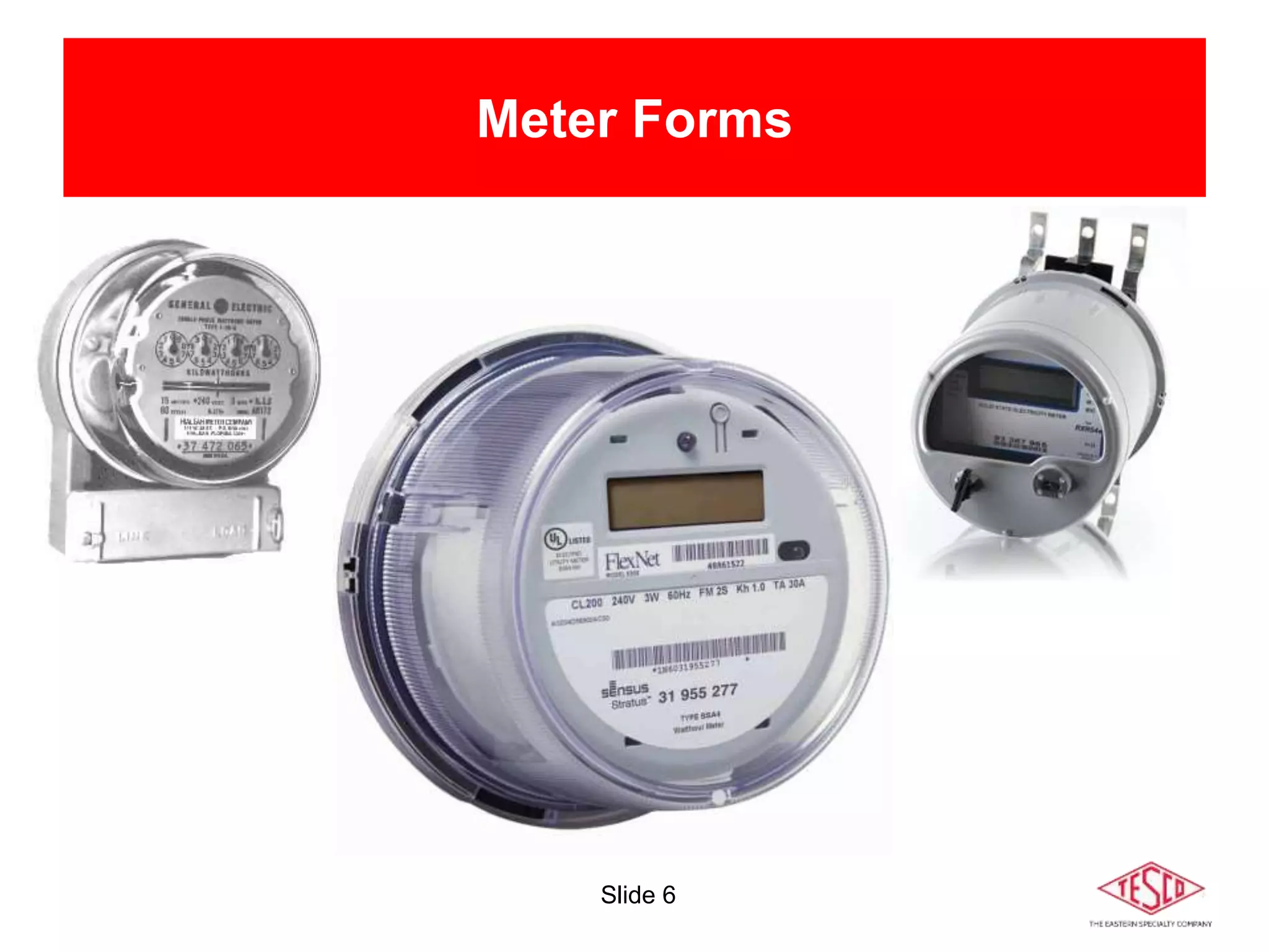
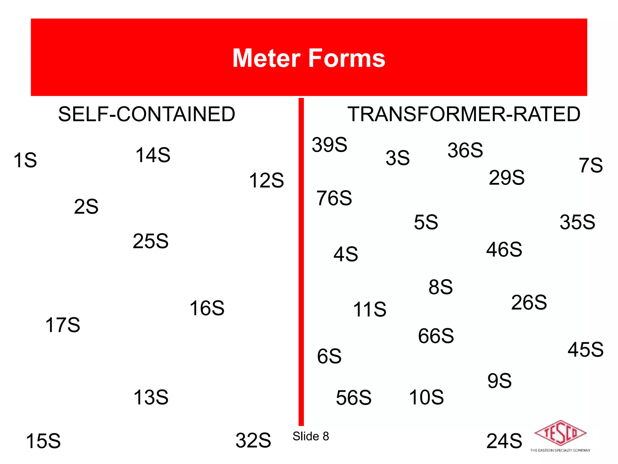
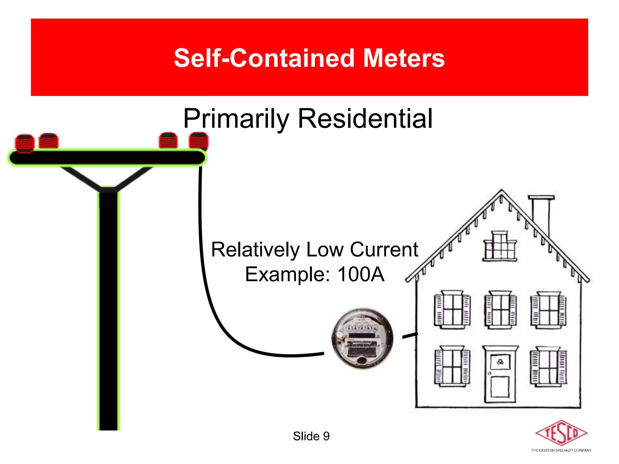
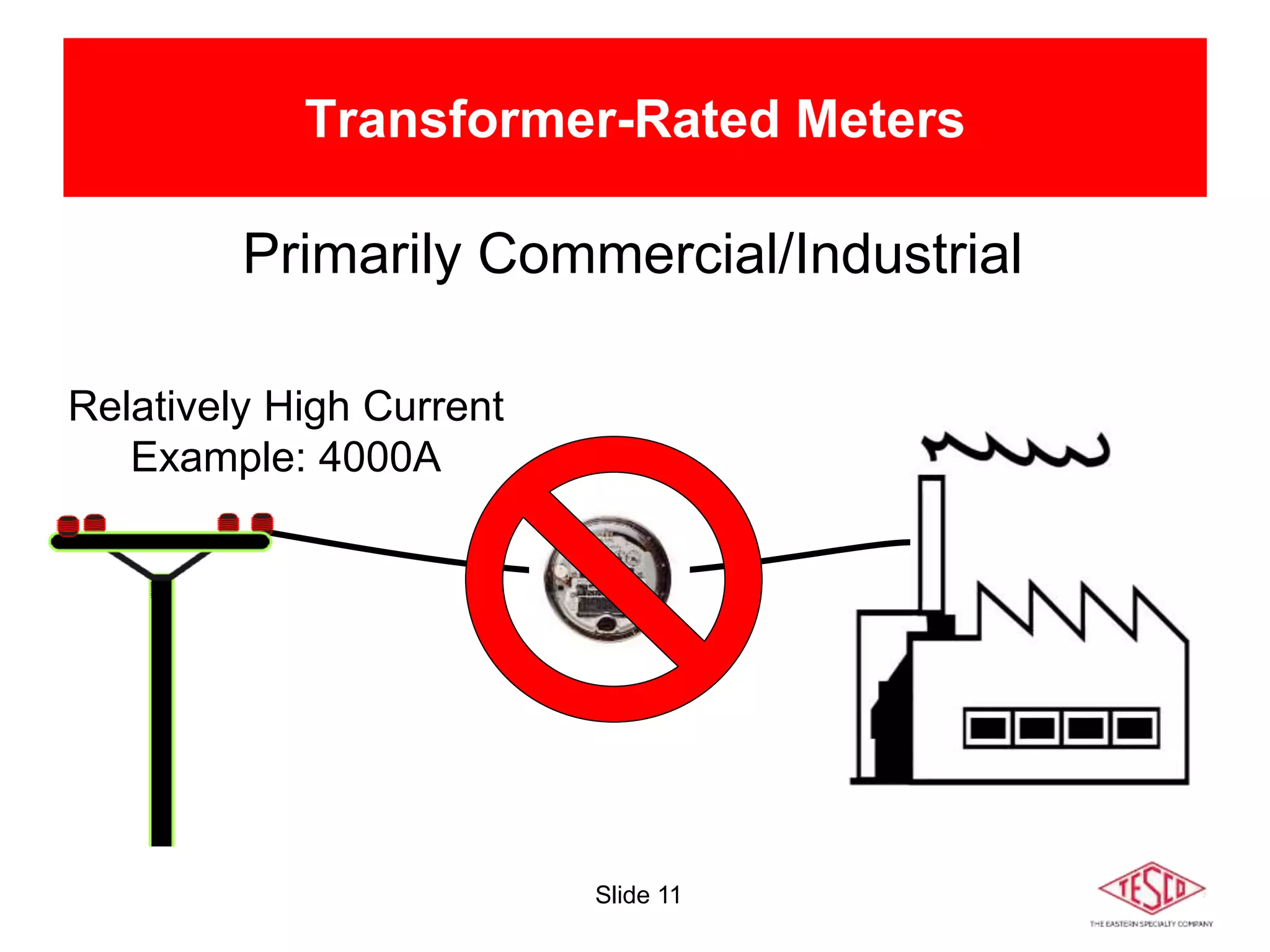
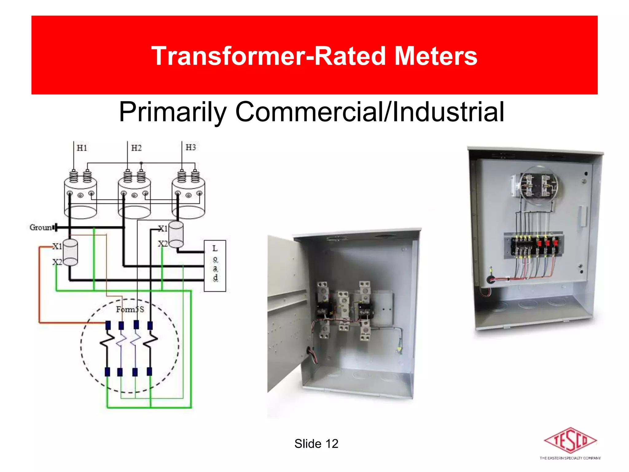
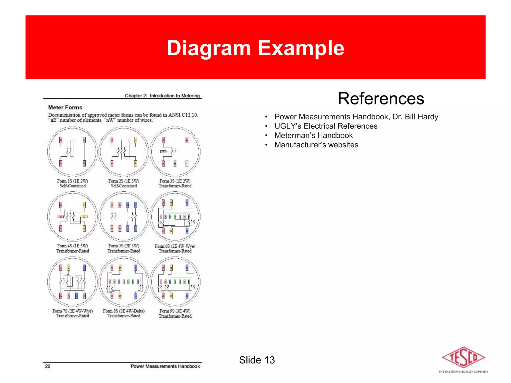
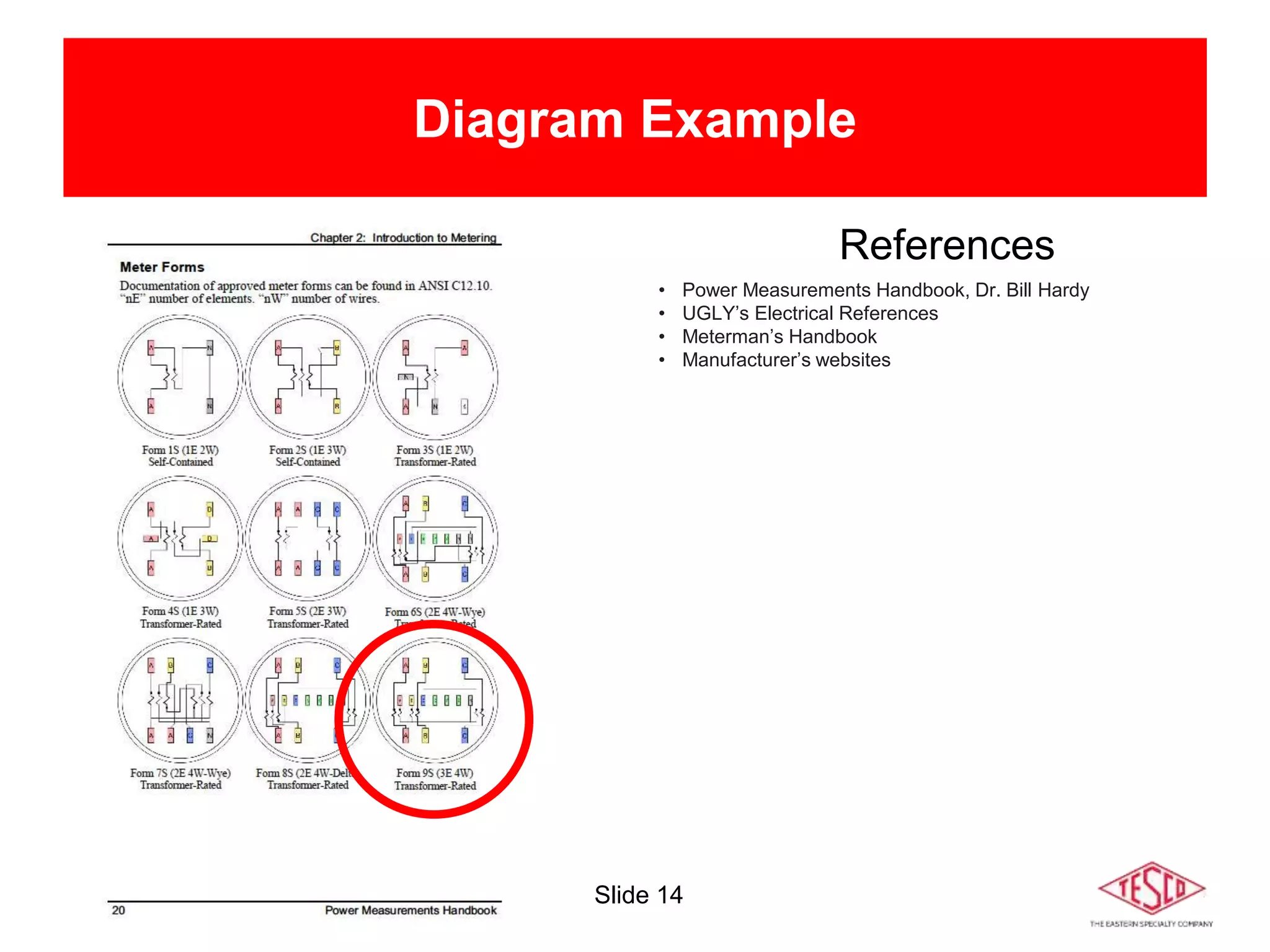
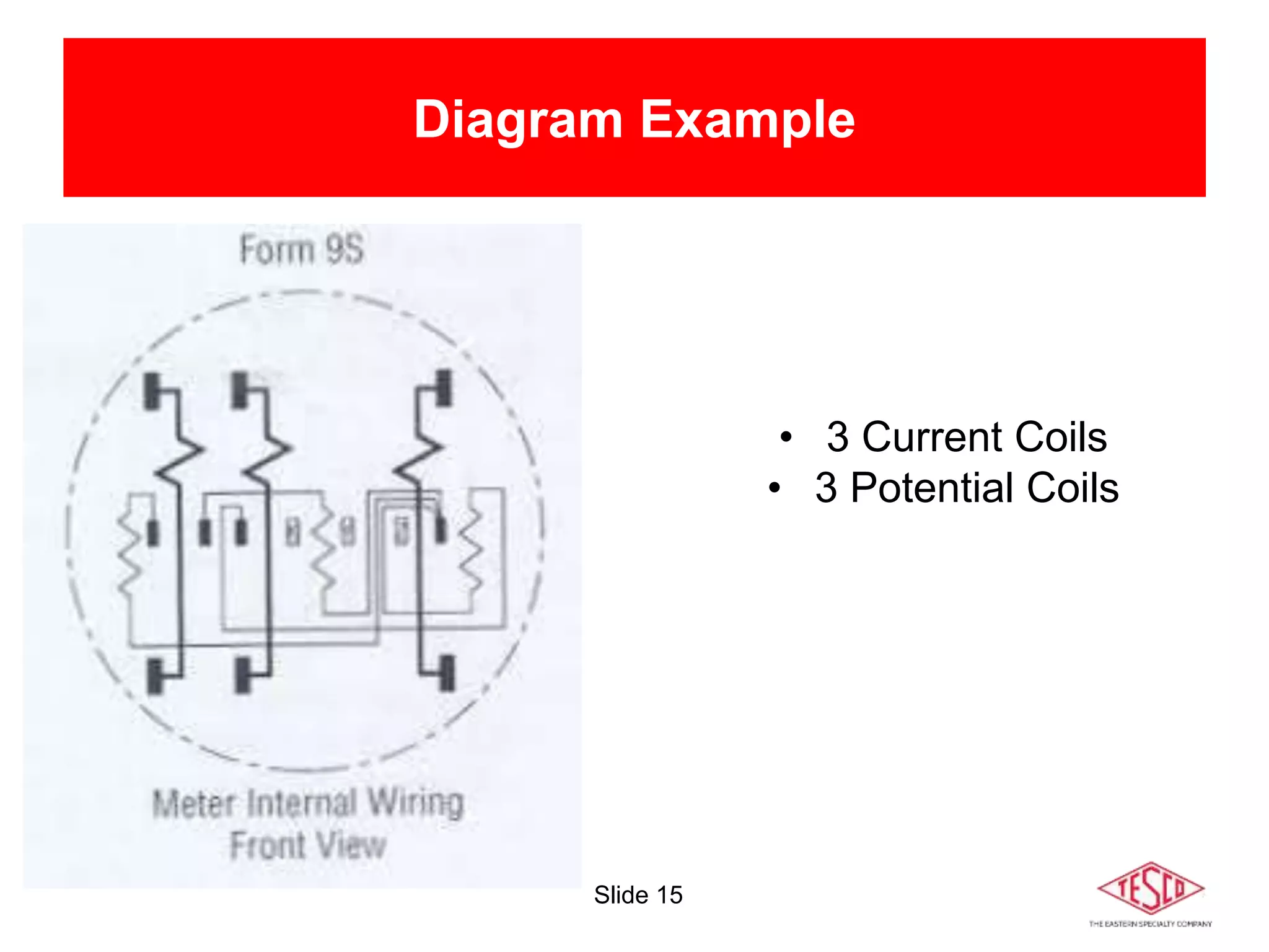
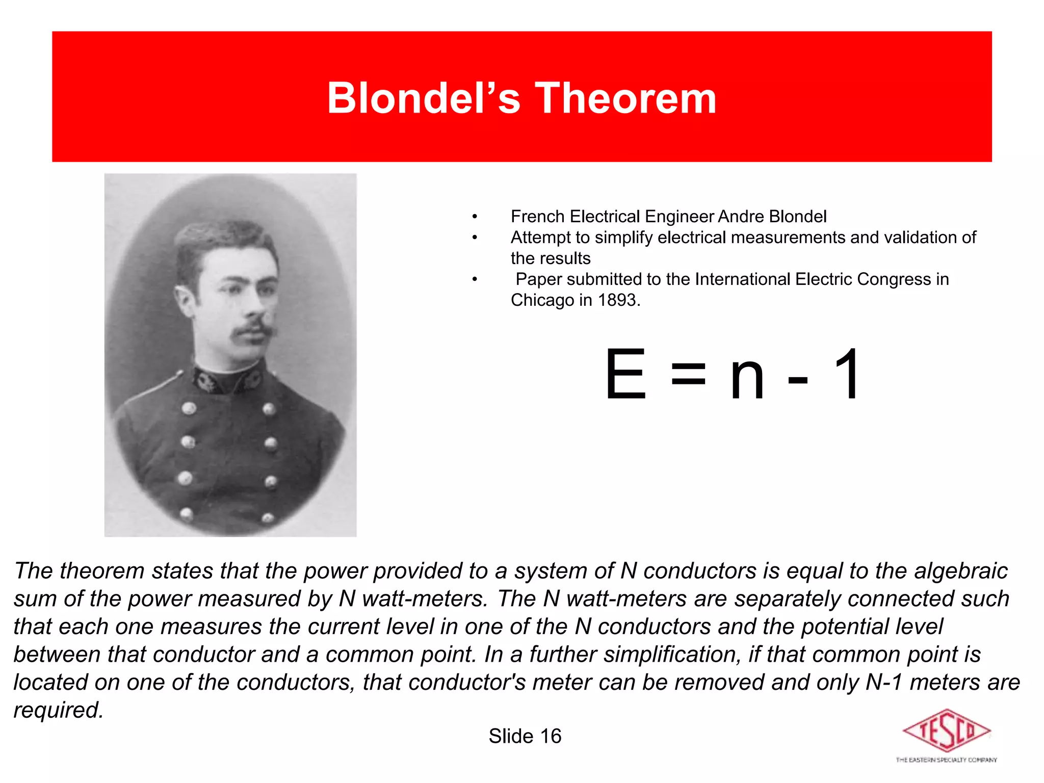
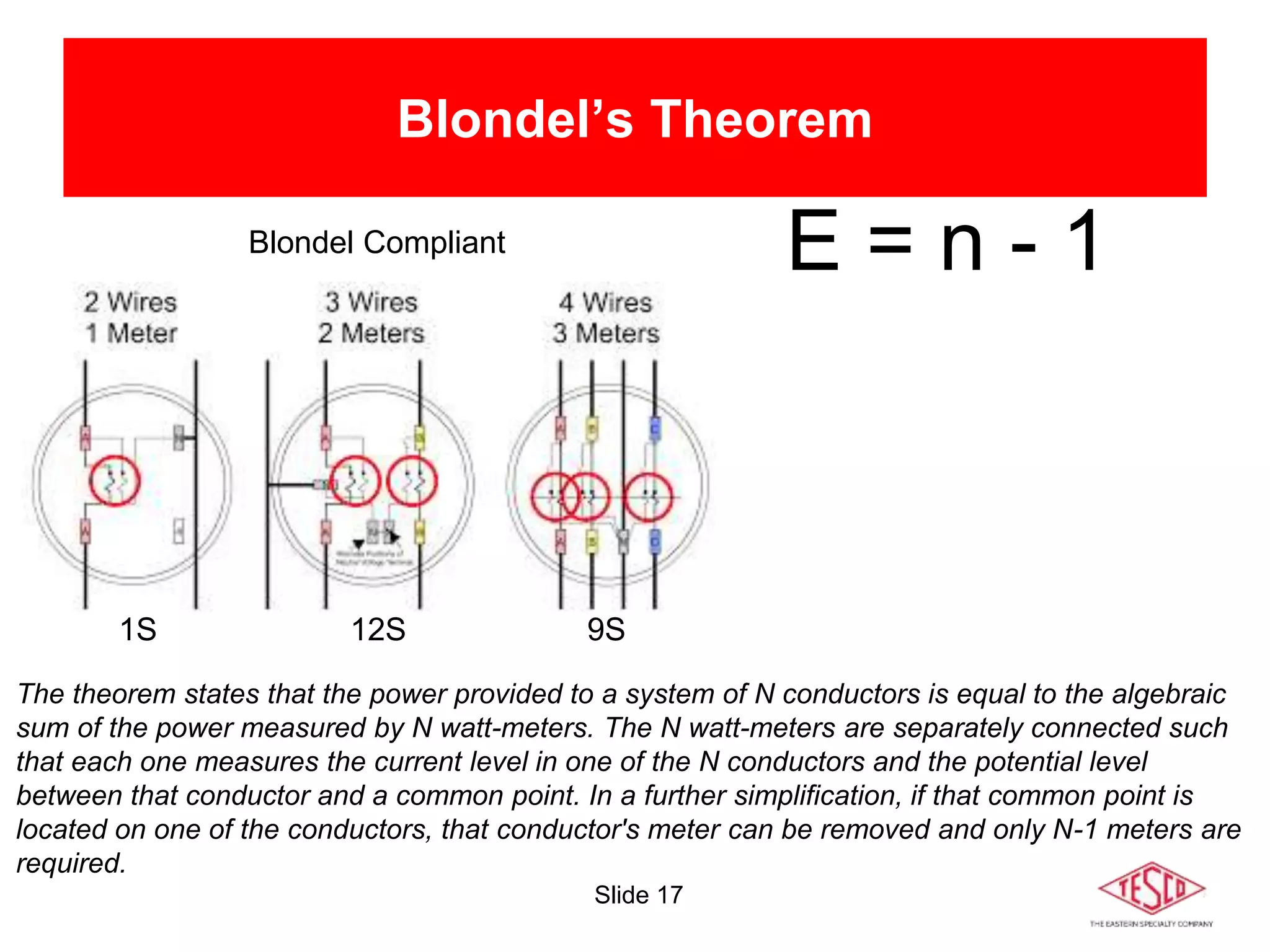
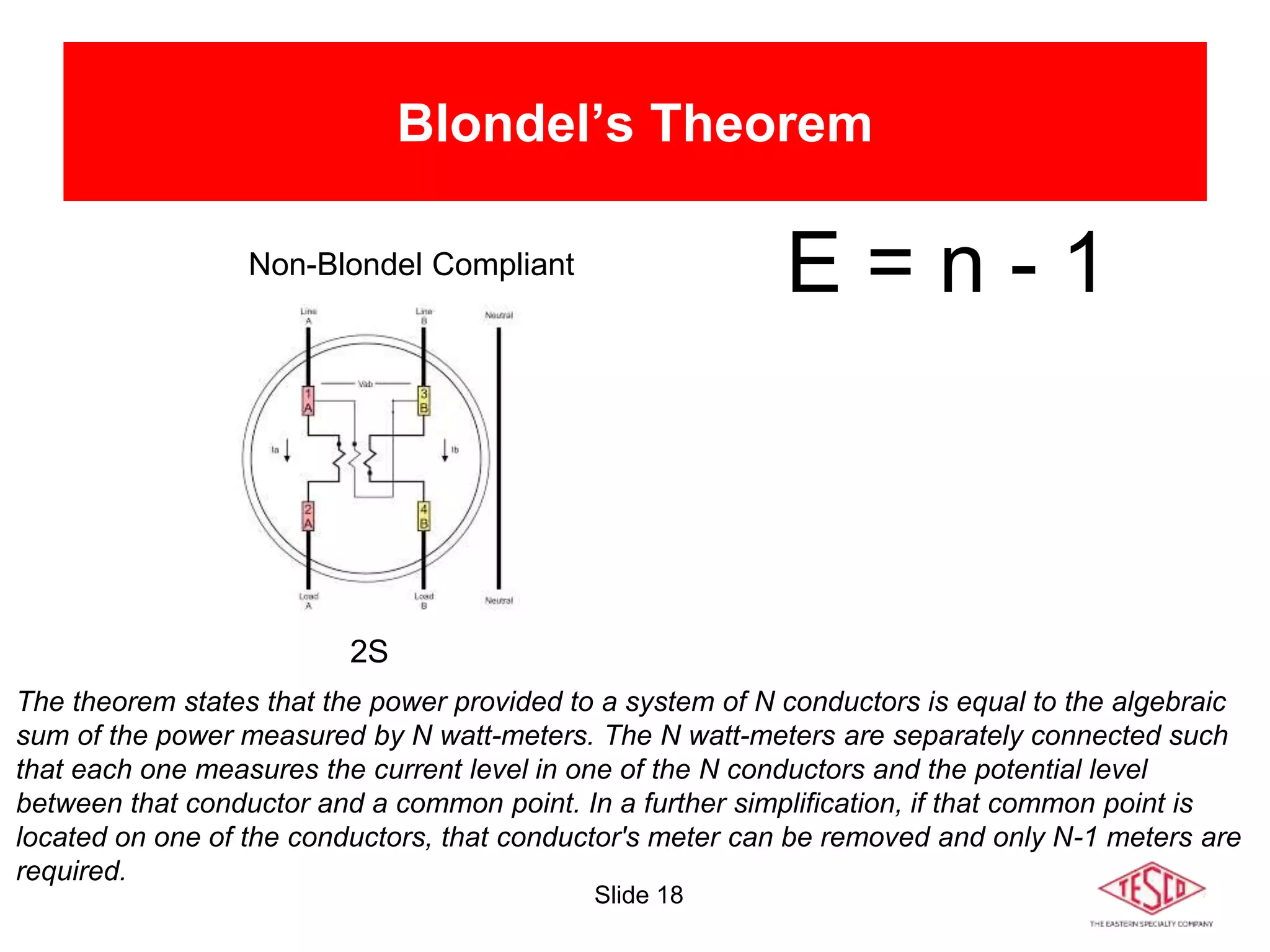
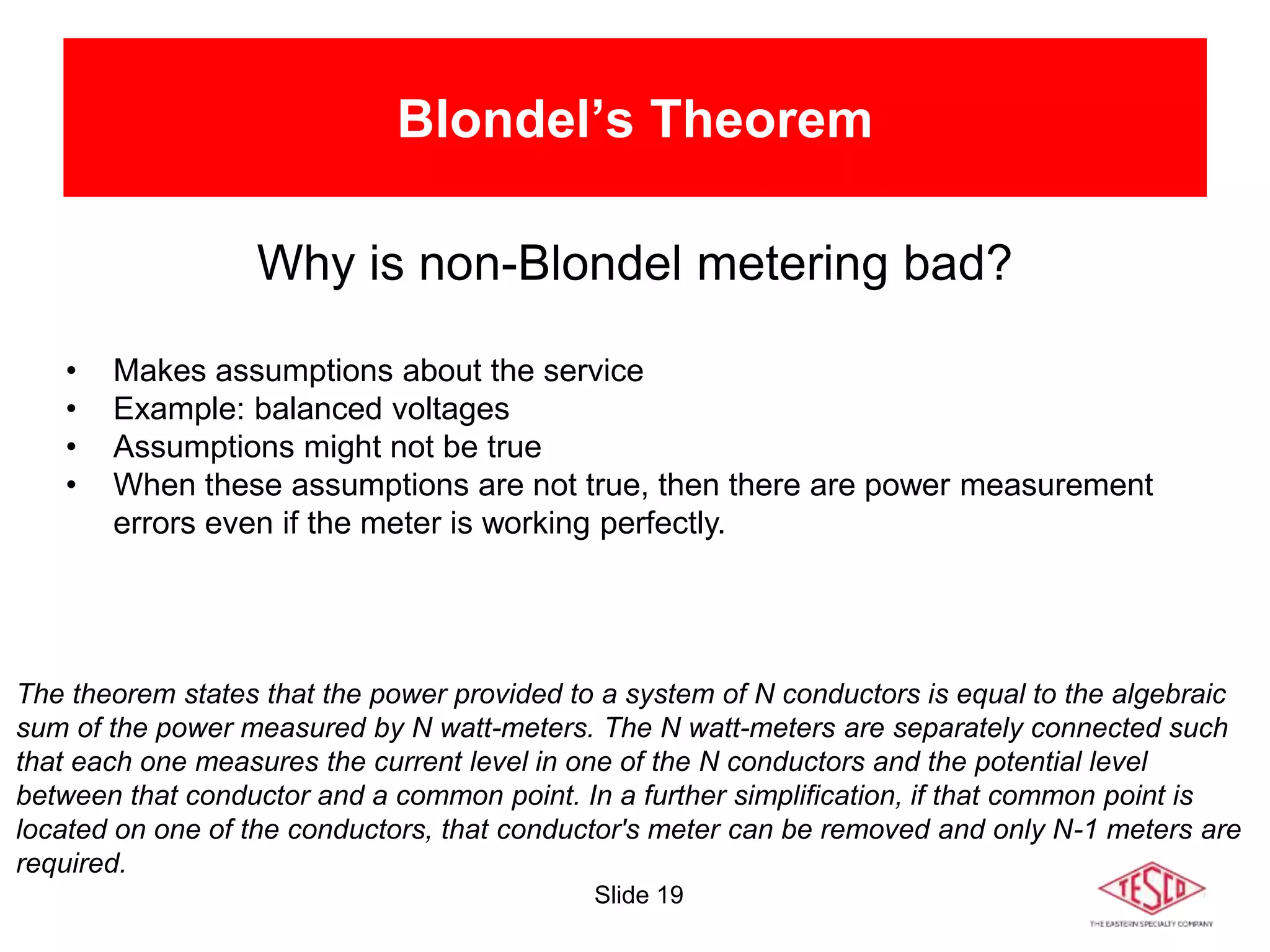
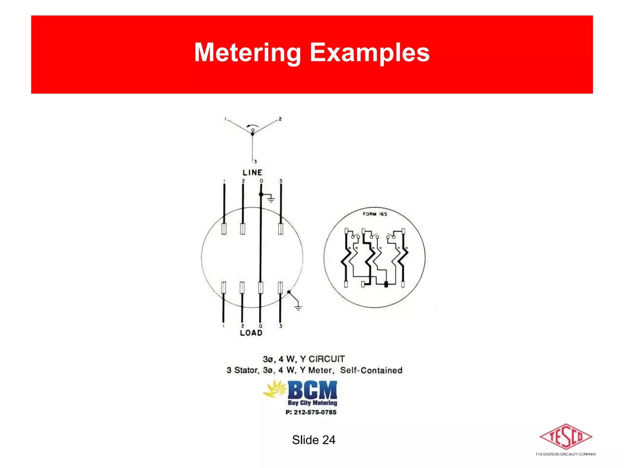
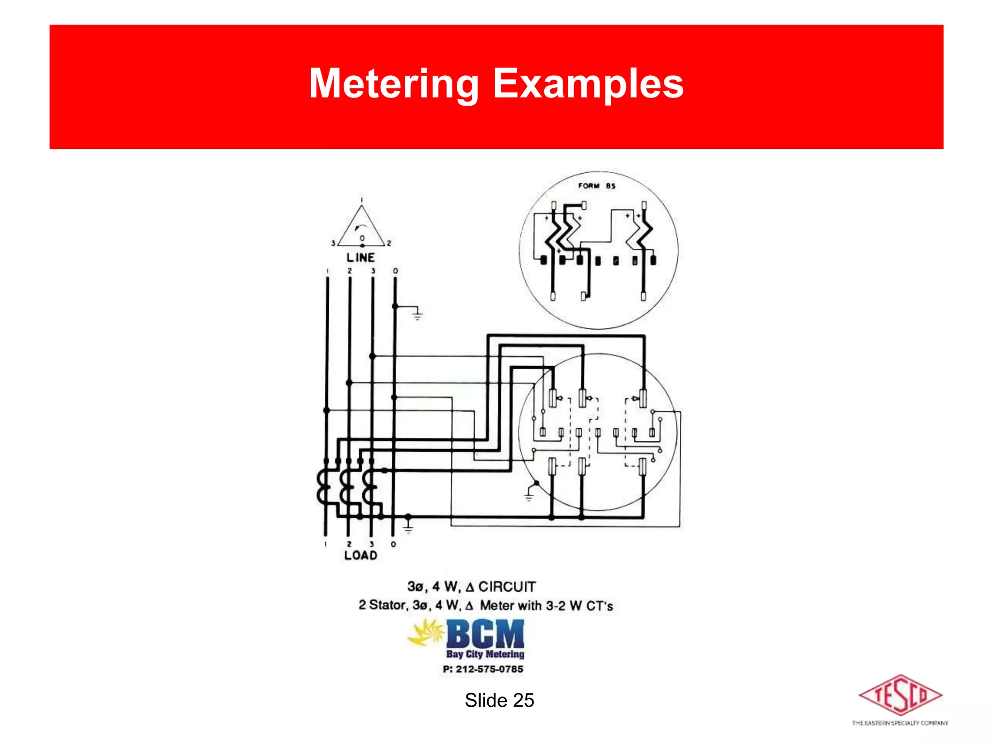
Slide 1
10/02/2012 Slide 1
Meter Forms:
Wiring and Uses
Prepared by Rob Reese, TESCO
The Eastern Specialty Company
for Pennsylvania Rural Electric Association
March 9, 2021
9:40 a.m. – 10:50 a.m.
Slide 2
Agenda
Meters 101 - Electro-Mechanical vs Solid-State
Meter Forms
Self-Contained vs Transformer Rated
Blondel’s Theorem
Available References (Hardy’s, UGLY’s Elect Ref)
Examples
1S, 2S, 3S, 4S, 5/35S, 8/9S, 16S
Slide 3
Meters 101 – Electro-mechanical
Overview of Functionality
• The electromechanical induction meter operates
through electromagnetic induction
• A non-magnetic, but electrically conductive, metal disc which is made to
rotate at a speed proportional to the power passing through the meter
• The disc is acted upon by two sets of induction coils, which form, in
effect, a two phase linear induction motor.
• One coil is connected in such a way that it produces a magnetic flux in
proportion to the voltage
• The other coil produces a magnetic flux in proportion to the current.
• The field of the voltage coil is delayed by 90 degrees, due to the coil's
inductive nature, and calibrated using a lag coil
• This produces eddy currents in the disc and the effect is such that
a force is exerted on the disc in proportion to the product of the
instantaneous current and instantaneous voltage
• A permanent magnet acts as an eddy current brake, exerting an
opposing force proportional to the speed of rotation of the disc
• The equilibrium between these two opposing forces results in the disc
rotating at a speed proportional to the power or rate of energy usage
• The disc drives a register mechanism which counts revolutions, much
like the odometer in a car, in order to render a measurement of the total
energy used.
• The amount of energy represented by one revolution of the disc is
denoted by the symbol Kh which is given in units of watt-hours per
revolution.
• A Kh of 7.2 is typical. In this example, each full rotation of the disk is
equivalent to 7.2Wh of energy.
Slide 4
Meters 101 – Solid-state
CURRENT
TRANSFORMER
POTENTIAL
TRANSFORMER
ADC
FILTER
ADC
FILTER
MICRO
PROC
DISPLAY
COMM
PULSE
Overview of Functionality
• Potential and Current is scaled down and conditioned with transformers and filters
• ADC’s (analog to digital converters) digitize the signals
• A micro-processor or DSP executes the calculations
• Resulting data is displayed, sent externally via the communication circuits, and used for the calibrated pulse output
Slide 5
Meter Forms
1S
2S
3S
4S
5S 6S
9S
12S
15S
16S
25S
45S
10S
11S
13S
14S 17S
24S
32S
39S
26S
35S
46S
56S
66S
76S
Slide 6
Meter Forms
Slide 7
Meter Forms
1S
2S
3S
4S
5S 6S
9S
12S
15S
16S
25S
45S
10S
11S
13S
14S 17S
24S
32S
39S
26S
35S
46S
56S
66S
76S
Slide 8
TRANSFORMER-RATED
Meter Forms
1S
2S
3S
4S
5S
6S
9S
12S
15S
16S
25S
45S
10S
11S
13S
14S
17S
24S
32S
39S
26S
35S
46S
56S
66S
76S
7S
8S
29S
36S
SELF-CONTAINED
Slide 9
Self-Contained Meters
Relatively Low Current
Example: 100A
Primarily Residential
Slide 10
Self-Contained
Primarily Residential
Slide 11
Transformer-Rated Meters
Relatively High Current
Example: 4000A
Primarily Commercial/Industrial
Slide 12
Transformer-Rated Meters
Primarily Commercial/Industrial
Slide 13
Diagram Example
References
• Power Measurements Handbook, Dr. Bill Hardy
• UGLY’s Electrical References
• Meterman’s Handbook
• Manufacturer’s websites
Slide 14
Diagram Example
References
• Power Measurements Handbook, Dr. Bill Hardy
• UGLY’s Electrical References
• Meterman’s Handbook
• Manufacturer’s websites
Slide 15
Diagram Example
• 3 Current Coils
• 3 Potential Coils
Slide 16
Blondel’s Theorem
• French Electrical Engineer Andre Blondel
• Attempt to simplify electrical measurements and validation of
the results
• Paper submitted to the International Electric Congress in
Chicago in 1893.
E = n - 1
The theorem states that the power provided to a system of N conductors is equal to the algebraic
sum of the power measured by N watt-meters. The N watt-meters are separately connected such
that each one measures the current level in one of the N conductors and the potential level
between that conductor and a common point. In a further simplification, if that common point is
located on one of the conductors, that conductor's meter can be removed and only N-1 meters are
required.
Slide 17
Blondel’s Theorem
E = n - 1
The theorem states that the power provided to a system of N conductors is equal to the algebraic
sum of the power measured by N watt-meters. The N watt-meters are separately connected such
that each one measures the current level in one of the N conductors and the potential level
between that conductor and a common point. In a further simplification, if that common point is
located on one of the conductors, that conductor's meter can be removed and only N-1 meters are
required.
1S 12S 9S
Blondel Compliant
Slide 18
Blondel’s Theorem
E = n - 1
The theorem states that the power provided to a system of N conductors is equal to the algebraic
sum of the power measured by N watt-meters. The N watt-meters are separately connected such
that each one measures the current level in one of the N conductors and the potential level
between that conductor and a common point. In a further simplification, if that common point is
located on one of the conductors, that conductor's meter can be removed and only N-1 meters are
required.
2S
Non-Blondel Compliant
Slide 19
Blondel’s Theorem
Why is non-Blondel metering bad?
• Makes assumptions about the service
• Example: balanced voltages
• Assumptions might not be true
• When these assumptions are not true, then there are power measurement
errors even if the meter is working perfectly.
The theorem states that the power provided to a system of N conductors is equal to the algebraic
sum of the power measured by N watt-meters. The N watt-meters are separately connected such
that each one measures the current level in one of the N conductors and the potential level
between that conductor and a common point. In a further simplification, if that common point is
located on one of the conductors, that conductor's meter can be removed and only N-1 meters are
required.
Slide 20
Blondel’s Theorem
Why are non-Blondel meters used?
• Fewer elements (meters) = lower cost
• Especially true for electro-mechanical meters
• Fewer CT’s and PT’s = lower cost
• Less wiring and cheaper sockets
The theorem states that the power provided to a system of N conductors is equal to the algebraic
sum of the power measured by N watt-meters. The N watt-meters are separately connected such
that each one measures the current level in one of the N conductors and the potential level
between that conductor and a common point. In a further simplification, if that common point is
located on one of the conductors, that conductor's meter can be removed and only N-1 meters are
required.
Slide 21
Metering Examples
Slide 22
Metering Examples
Slide 23
Metering Examples
Slide 24
Metering Examples
Slide 25
Metering Examples
Slide 26
References
• https://en.wikipedia.org/wiki/Blondel%27s_theorem
• http://www.powermeasurements.org/library/Presentations/NCMS%202013%
20-%20Non-Blondel%20Metering.pdf
• https://www.baycitymetering.com/
Slide 27
Questions and Discussion
Rob Reese
rob.reese@tescometering.com
TESCO – The Eastern Specialty Company
Bristol, PA
215-310-8809 (cell)
This presentation can also be found under Meter Conferences and
Schools on the TESCO website: www.tescometering.com
ISO 9001:2015 Certified Quality Company
ISO 17025:2017 Accredited Laboratory

Meter Forms: Wiring and Uses

  • 1.
    Slide 1 10/02/2012 Slide1 Meter Forms: Wiring and Uses Prepared by Rob Reese, TESCO The Eastern Specialty Company for Pennsylvania Rural Electric Association March 9, 2021 9:40 a.m. – 10:50 a.m.
  • 2.
    Slide 2 Agenda Meters 101- Electro-Mechanical vs Solid-State Meter Forms Self-Contained vs Transformer Rated Blondel’s Theorem Available References (Hardy’s, UGLY’s Elect Ref) Examples 1S, 2S, 3S, 4S, 5/35S, 8/9S, 16S
  • 3.
    Slide 3 Meters 101– Electro-mechanical Overview of Functionality • The electromechanical induction meter operates through electromagnetic induction • A non-magnetic, but electrically conductive, metal disc which is made to rotate at a speed proportional to the power passing through the meter • The disc is acted upon by two sets of induction coils, which form, in effect, a two phase linear induction motor. • One coil is connected in such a way that it produces a magnetic flux in proportion to the voltage • The other coil produces a magnetic flux in proportion to the current. • The field of the voltage coil is delayed by 90 degrees, due to the coil's inductive nature, and calibrated using a lag coil • This produces eddy currents in the disc and the effect is such that a force is exerted on the disc in proportion to the product of the instantaneous current and instantaneous voltage • A permanent magnet acts as an eddy current brake, exerting an opposing force proportional to the speed of rotation of the disc • The equilibrium between these two opposing forces results in the disc rotating at a speed proportional to the power or rate of energy usage • The disc drives a register mechanism which counts revolutions, much like the odometer in a car, in order to render a measurement of the total energy used. • The amount of energy represented by one revolution of the disc is denoted by the symbol Kh which is given in units of watt-hours per revolution. • A Kh of 7.2 is typical. In this example, each full rotation of the disk is equivalent to 7.2Wh of energy.
  • 4.
    Slide 4 Meters 101– Solid-state CURRENT TRANSFORMER POTENTIAL TRANSFORMER ADC FILTER ADC FILTER MICRO PROC DISPLAY COMM PULSE Overview of Functionality • Potential and Current is scaled down and conditioned with transformers and filters • ADC’s (analog to digital converters) digitize the signals • A micro-processor or DSP executes the calculations • Resulting data is displayed, sent externally via the communication circuits, and used for the calibrated pulse output
  • 5.
    Slide 5 Meter Forms 1S 2S 3S 4S 5S6S 9S 12S 15S 16S 25S 45S 10S 11S 13S 14S 17S 24S 32S 39S 26S 35S 46S 56S 66S 76S
  • 6.
  • 7.
    Slide 7 Meter Forms 1S 2S 3S 4S 5S6S 9S 12S 15S 16S 25S 45S 10S 11S 13S 14S 17S 24S 32S 39S 26S 35S 46S 56S 66S 76S
  • 8.
  • 9.
    Slide 9 Self-Contained Meters RelativelyLow Current Example: 100A Primarily Residential
  • 10.
  • 11.
    Slide 11 Transformer-Rated Meters RelativelyHigh Current Example: 4000A Primarily Commercial/Industrial
  • 12.
  • 13.
    Slide 13 Diagram Example References •Power Measurements Handbook, Dr. Bill Hardy • UGLY’s Electrical References • Meterman’s Handbook • Manufacturer’s websites
  • 14.
    Slide 14 Diagram Example References •Power Measurements Handbook, Dr. Bill Hardy • UGLY’s Electrical References • Meterman’s Handbook • Manufacturer’s websites
  • 15.
    Slide 15 Diagram Example •3 Current Coils • 3 Potential Coils
  • 16.
    Slide 16 Blondel’s Theorem •French Electrical Engineer Andre Blondel • Attempt to simplify electrical measurements and validation of the results • Paper submitted to the International Electric Congress in Chicago in 1893. E = n - 1 The theorem states that the power provided to a system of N conductors is equal to the algebraic sum of the power measured by N watt-meters. The N watt-meters are separately connected such that each one measures the current level in one of the N conductors and the potential level between that conductor and a common point. In a further simplification, if that common point is located on one of the conductors, that conductor's meter can be removed and only N-1 meters are required.
  • 17.
    Slide 17 Blondel’s Theorem E= n - 1 The theorem states that the power provided to a system of N conductors is equal to the algebraic sum of the power measured by N watt-meters. The N watt-meters are separately connected such that each one measures the current level in one of the N conductors and the potential level between that conductor and a common point. In a further simplification, if that common point is located on one of the conductors, that conductor's meter can be removed and only N-1 meters are required. 1S 12S 9S Blondel Compliant
  • 18.
    Slide 18 Blondel’s Theorem E= n - 1 The theorem states that the power provided to a system of N conductors is equal to the algebraic sum of the power measured by N watt-meters. The N watt-meters are separately connected such that each one measures the current level in one of the N conductors and the potential level between that conductor and a common point. In a further simplification, if that common point is located on one of the conductors, that conductor's meter can be removed and only N-1 meters are required. 2S Non-Blondel Compliant
  • 19.
    Slide 19 Blondel’s Theorem Whyis non-Blondel metering bad? • Makes assumptions about the service • Example: balanced voltages • Assumptions might not be true • When these assumptions are not true, then there are power measurement errors even if the meter is working perfectly. The theorem states that the power provided to a system of N conductors is equal to the algebraic sum of the power measured by N watt-meters. The N watt-meters are separately connected such that each one measures the current level in one of the N conductors and the potential level between that conductor and a common point. In a further simplification, if that common point is located on one of the conductors, that conductor's meter can be removed and only N-1 meters are required.
  • 20.
    Slide 20 Blondel’s Theorem Whyare non-Blondel meters used? • Fewer elements (meters) = lower cost • Especially true for electro-mechanical meters • Fewer CT’s and PT’s = lower cost • Less wiring and cheaper sockets The theorem states that the power provided to a system of N conductors is equal to the algebraic sum of the power measured by N watt-meters. The N watt-meters are separately connected such that each one measures the current level in one of the N conductors and the potential level between that conductor and a common point. In a further simplification, if that common point is located on one of the conductors, that conductor's meter can be removed and only N-1 meters are required.
  • 21.
  • 22.
  • 23.
  • 24.
  • 25.
  • 26.
    Slide 26 References • https://en.wikipedia.org/wiki/Blondel%27s_theorem •http://www.powermeasurements.org/library/Presentations/NCMS%202013% 20-%20Non-Blondel%20Metering.pdf • https://www.baycitymetering.com/
  • 27.
    Slide 27 Questions andDiscussion Rob Reese rob.reese@tescometering.com TESCO – The Eastern Specialty Company Bristol, PA 215-310-8809 (cell) This presentation can also be found under Meter Conferences and Schools on the TESCO website: www.tescometering.com ISO 9001:2015 Certified Quality Company ISO 17025:2017 Accredited Laboratory