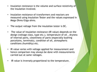
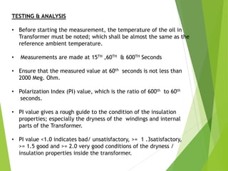
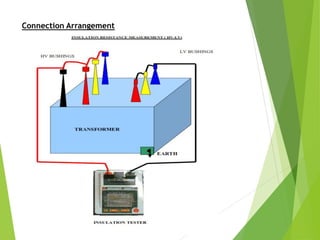
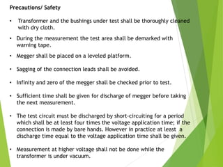
TRANSFORMER TESTING
Insulation Resistance
Shanid Pazhamkavil
INSULATION RESISTANCE TESTING
• Insulation resistance measurements are performed to verify
that the state of dryness of the insulation of the various
windings and the core are of acceptable values.
• Insulation resistance testing may also reveal important
information about concealed damage of bushings.
• Insulation resistance is the volume and surface resistivity of
the insulation involved.
• Insulation resistance of transformers and reactors are
measured using Insulation Tester and the values expressed in
Mega Ohms/Giga ohms.
• The output voltage from the insulation tester is DC.
• The value of insulation resistance (IR value) depends on the
design (voltage class, type etc.), temperature of oil , dryness
of internal parts, cleanliness of parts (especially bushing
porcelains, terminals), condition of oil, atmospheric
conditions (humidity) etc.
• IR value varies with voltage applied for measurement and
hence comparison may always be done with measurements
carried out at same voltages.
• IR value is inversely proportional to the temperature.
TESTING & ANALYSIS
• Before starting the measurement, the temperature of the oil in
Transformer must be noted; which shall be almost the same as the
reference ambient temperature.
• Measurements are made at 15TH ,60TH & 600TH Seconds
• Ensure that the measured value at 60th seconds is not less than
2000 Meg. Ohm.
• Polarization Index (PI) value, which is the ratio of 600th to 60th
seconds.
• PI value gives a rough guide to the condition of the insulation
properties; especially the dryness of the windings and internal
parts of the Transformer.
• PI value <1.0 indicates bad/ unsatisfactory, >= 1 .3satisfactory,
>= 1.5 good and >= 2.0 very good conditions of the dryness /
insulation properties inside the transformer.
• The new generation Insulation testers have inbuilt provisions for discharging
the voltages through the testing equipment itself, which takes place within a
few seconds after switching off. However ,as the voltage generated for
measurement is of the tune of 500V ~ 5000V, earthing may be done
externally before removing the connections as a safety precaution
Insulation Resistance of Winding
Aim
c) To determine the insulation resistance of individual winding
to Earth and between windings.
d) To evaluate the condition of the Transformer insulation.
Test preparation
• Insulation Tester (Megger) must be of 5kV range having valid
calibration.
• The earthing of the main body / tank, core /clamp etc.,
cleanliness & dryness of the bushing porcelains/ terminals
and tightness of the connection are checked.
• The temperature of the oil inside the transformer (OTI
reading) is noted.
• Care may be taken to see that test leads do not touch among
themselves and with Transformer body.
Test procedure
• Terminals of all HV bushings and HVN bushing are shorted
together as shown in the figure. Similarly all terminals of LV
bushings are shorted together.
• The test voltage is selected per the requirement considering
the voltage class of the testing specimen
• IR values of individual winding to Earth and between windings
are measured at 15th ,60th and 600th seconds.
• Compare the measured IR values with the factory results. Also
evaluate PI values.
• Connection diagram for a two winding Transformer is shown
below.
*Vector Indication may change according to vector group of transformer
*Ynd vector group is considered in above diagram
Connection Arrangement
How the instrument looks like?
Precautions/ Safety
• Transformer and the bushings under test shall be thoroughly cleaned
with dry cloth.
• During the measurement the test area shall be demarked with
warning tape.
• Megger shall be placed on a leveled platform.
• Sagging of the connection leads shall be avoided.
• Infinity and zero of the megger shall be checked prior to test.
• Sufficient time shall be given for discharge of megger before taking
the next measurement.
• The test circuit must be discharged by short-circuiting for a period
which shall be at least four times the voltage application time; if the
connection is made by bare hands. However in practice at least a
discharge time equal to the voltage application time shall be given.
• Measurement at higher voltage shall not be done while the
transformer is under vacuum.
Interpretation
• A high value of polarization index indicates the insulation is very
good. PI value <1 indicates immediate corrective action is
required.
• There are no specific absolute values of acceptable insulation
resistance; however reference should be made to previous test
history to establish a trend.

Insulation Resistance Test

  • 1.
  • 2.
    INSULATION RESISTANCE TESTING •Insulation resistance measurements are performed to verify that the state of dryness of the insulation of the various windings and the core are of acceptable values. • Insulation resistance testing may also reveal important information about concealed damage of bushings.
  • 3.
    • Insulation resistanceis the volume and surface resistivity of the insulation involved. • Insulation resistance of transformers and reactors are measured using Insulation Tester and the values expressed in Mega Ohms/Giga ohms. • The output voltage from the insulation tester is DC. • The value of insulation resistance (IR value) depends on the design (voltage class, type etc.), temperature of oil , dryness of internal parts, cleanliness of parts (especially bushing porcelains, terminals), condition of oil, atmospheric conditions (humidity) etc. • IR value varies with voltage applied for measurement and hence comparison may always be done with measurements carried out at same voltages. • IR value is inversely proportional to the temperature.
  • 4.
    TESTING & ANALYSIS •Before starting the measurement, the temperature of the oil in Transformer must be noted; which shall be almost the same as the reference ambient temperature. • Measurements are made at 15TH ,60TH & 600TH Seconds • Ensure that the measured value at 60th seconds is not less than 2000 Meg. Ohm. • Polarization Index (PI) value, which is the ratio of 600th to 60th seconds. • PI value gives a rough guide to the condition of the insulation properties; especially the dryness of the windings and internal parts of the Transformer. • PI value <1.0 indicates bad/ unsatisfactory, >= 1 .3satisfactory, >= 1.5 good and >= 2.0 very good conditions of the dryness / insulation properties inside the transformer.
  • 5.
    • The newgeneration Insulation testers have inbuilt provisions for discharging the voltages through the testing equipment itself, which takes place within a few seconds after switching off. However ,as the voltage generated for measurement is of the tune of 500V ~ 5000V, earthing may be done externally before removing the connections as a safety precaution
  • 6.
    Insulation Resistance ofWinding Aim c) To determine the insulation resistance of individual winding to Earth and between windings. d) To evaluate the condition of the Transformer insulation. Test preparation • Insulation Tester (Megger) must be of 5kV range having valid calibration. • The earthing of the main body / tank, core /clamp etc., cleanliness & dryness of the bushing porcelains/ terminals and tightness of the connection are checked. • The temperature of the oil inside the transformer (OTI reading) is noted. • Care may be taken to see that test leads do not touch among themselves and with Transformer body.
  • 7.
    Test procedure • Terminalsof all HV bushings and HVN bushing are shorted together as shown in the figure. Similarly all terminals of LV bushings are shorted together. • The test voltage is selected per the requirement considering the voltage class of the testing specimen • IR values of individual winding to Earth and between windings are measured at 15th ,60th and 600th seconds. • Compare the measured IR values with the factory results. Also evaluate PI values. • Connection diagram for a two winding Transformer is shown below.
  • 8.
    *Vector Indication maychange according to vector group of transformer *Ynd vector group is considered in above diagram
  • 9.
  • 10.
    How the instrumentlooks like?
  • 11.
    Precautions/ Safety • Transformerand the bushings under test shall be thoroughly cleaned with dry cloth. • During the measurement the test area shall be demarked with warning tape. • Megger shall be placed on a leveled platform. • Sagging of the connection leads shall be avoided. • Infinity and zero of the megger shall be checked prior to test. • Sufficient time shall be given for discharge of megger before taking the next measurement. • The test circuit must be discharged by short-circuiting for a period which shall be at least four times the voltage application time; if the connection is made by bare hands. However in practice at least a discharge time equal to the voltage application time shall be given. • Measurement at higher voltage shall not be done while the transformer is under vacuum.
  • 12.
    Interpretation • A highvalue of polarization index indicates the insulation is very good. PI value <1 indicates immediate corrective action is required. • There are no specific absolute values of acceptable insulation resistance; however reference should be made to previous test history to establish a trend.