This document discusses various methods for measuring electrical quantities like voltage, current and resistance. It begins by describing potentiometers and their use in DC voltage measurements. It then discusses different types of bridges including Wheatstone, Kelvin and Maxwell bridges which are used to measure resistances and impedances. The document also covers topics like electrostatic and electromagnetic interference, grounding techniques and references.
COMPARITIVE METHODS OF
MEASUREMENTS
KongunaduCollege of Engineering and Technology
Contents:
DC Potentiometer and Applications
DC Bridges
AC Bridges
Electro Static and Electro Magnetic Interference
Grounding Techniques
References
2.
DC Potentiometer
Apotentiometer is an instrument designed to measure an
unknown voltage by comparing it with a known voltage. The
known voltage may be supplied by a standard cell or any other
known voltage reference source .
Measurements using comparison methods are capable of a high
degree of accuracy because the result obtained does not depend
upon the actual deflection of a pointer, as is the case in
deflectional methods, but only upon the accuracy with which
the voltage of the reference source is known.
Kongunadu College of Engineering and Technology
3.
Types
Slide wireDC Potentiometer
Standardization of Potentiometer
Crompton’s DC Potentiometer
Duo-Range Potentiometer
Vernier Potentiometer
Kongunadu College of Engineering and Technology
4.
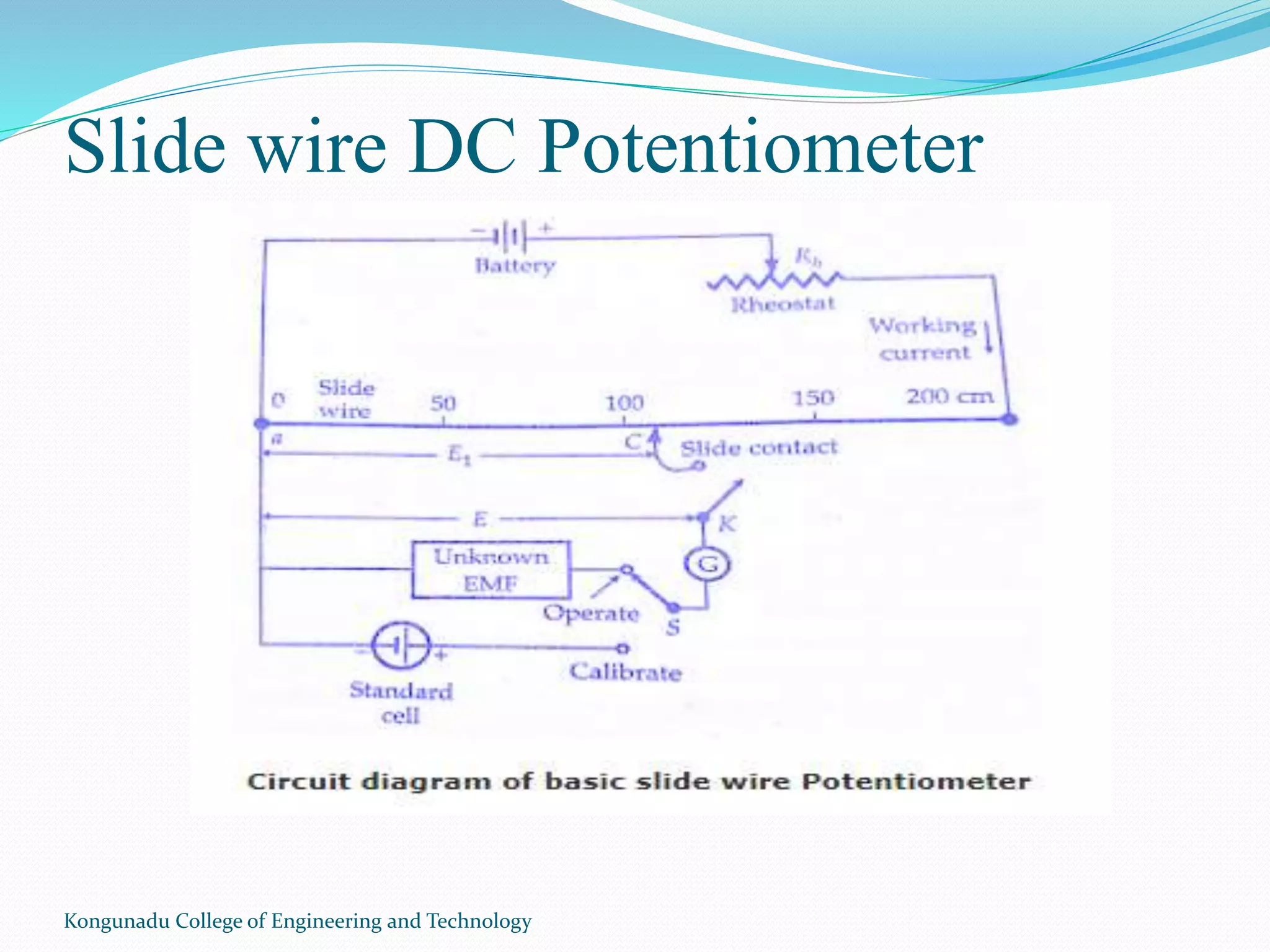
Slide wire DCPotentiometer
Kongunadu College of Engineering and Technology
5.
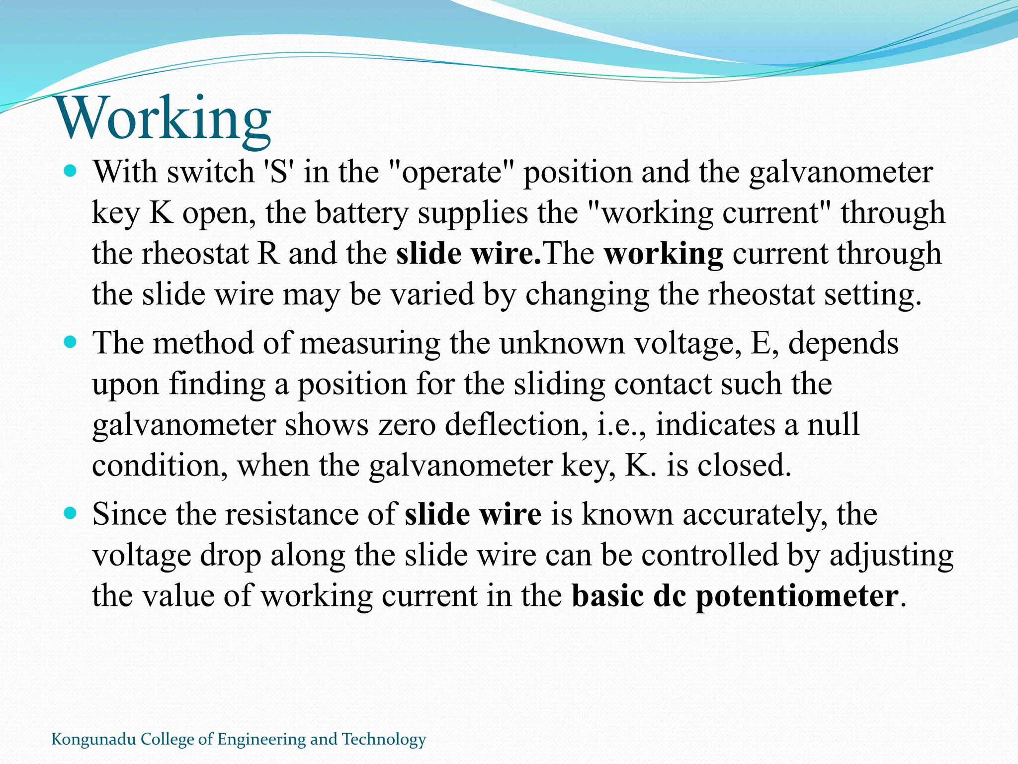
Working
With switch'S' in the "operate" position and the galvanometer
key K open, the battery supplies the "working current" through
the rheostat R and the slide wire.The working current through
the slide wire may be varied by changing the rheostat setting.
The method of measuring the unknown voltage, E, depends
upon finding a position for the sliding contact such the
galvanometer shows zero deflection, i.e., indicates a null
condition, when the galvanometer key, K. is closed.
Since the resistance of slide wire is known accurately, the
voltage drop along the slide wire can be controlled by adjusting
the value of working current in the basic dc potentiometer.
Kongunadu College of Engineering and Technology
6.
Cont…
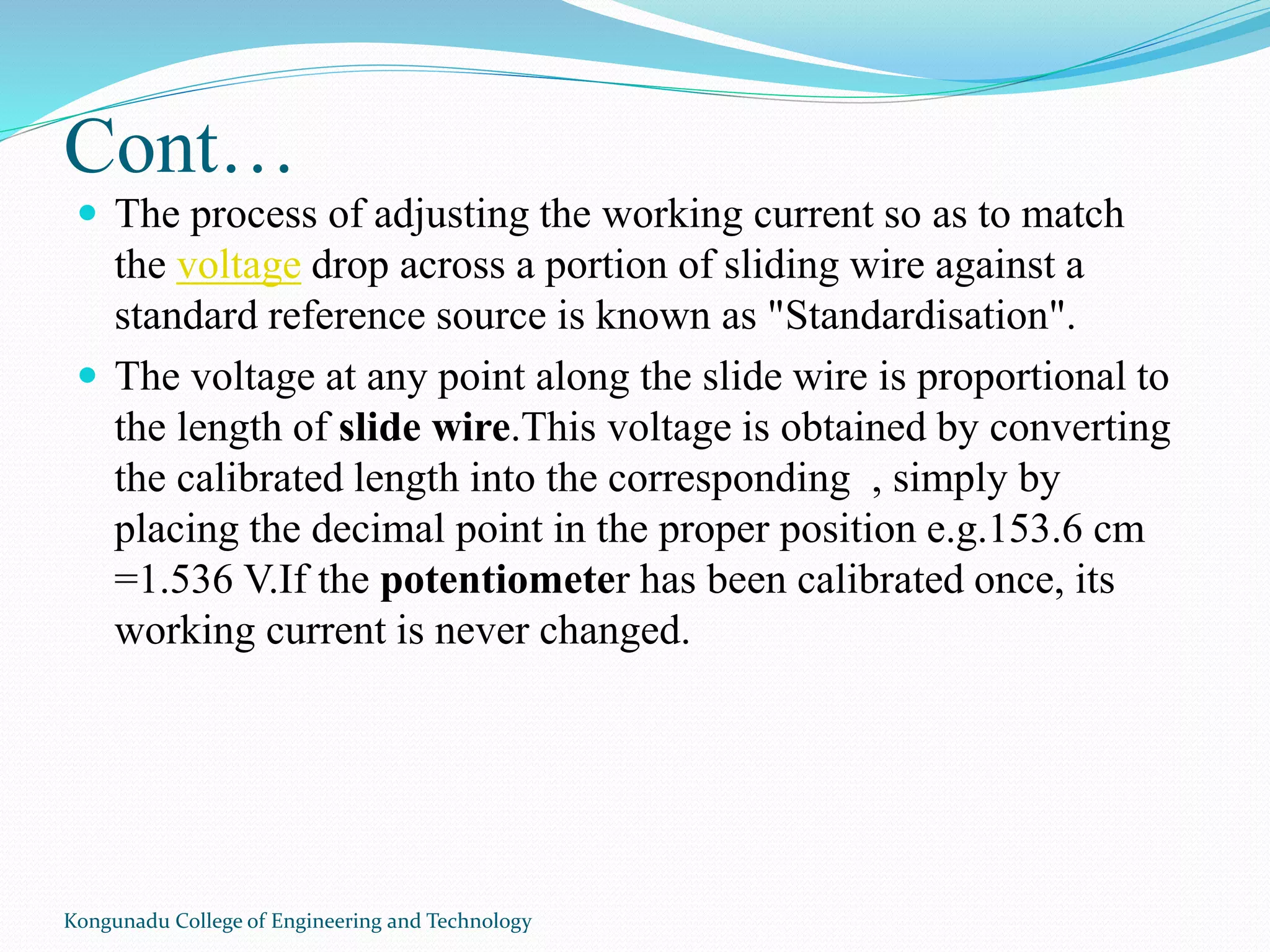
The processof adjusting the working current so as to match
the voltage drop across a portion of sliding wire against a
standard reference source is known as "Standardisation".
The voltage at any point along the slide wire is proportional to
the length of slide wire.This voltage is obtained by converting
the calibrated length into the corresponding , simply by
placing the decimal point in the proper position e.g.153.6 cm
=1.536 V.If the potentiometer has been calibrated once, its
working current is never changed.
Kongunadu College of Engineering and Technology
Cont…
Draw backof slide wire potentiometer is that its accuracy
depends on uniformity of the wire
Crompton dc potentiometer is a modified form of slide wire
potentiometer where calibrated slide resistors with a small
circular wire of one or more turns thus reducing the size of the
equipment
The effect of very long slide wire is obtained by connecting a
number of resistance coils in series with a comparatively short
wire
Kongunadu College of Engineering and Technology
9.
Cont…
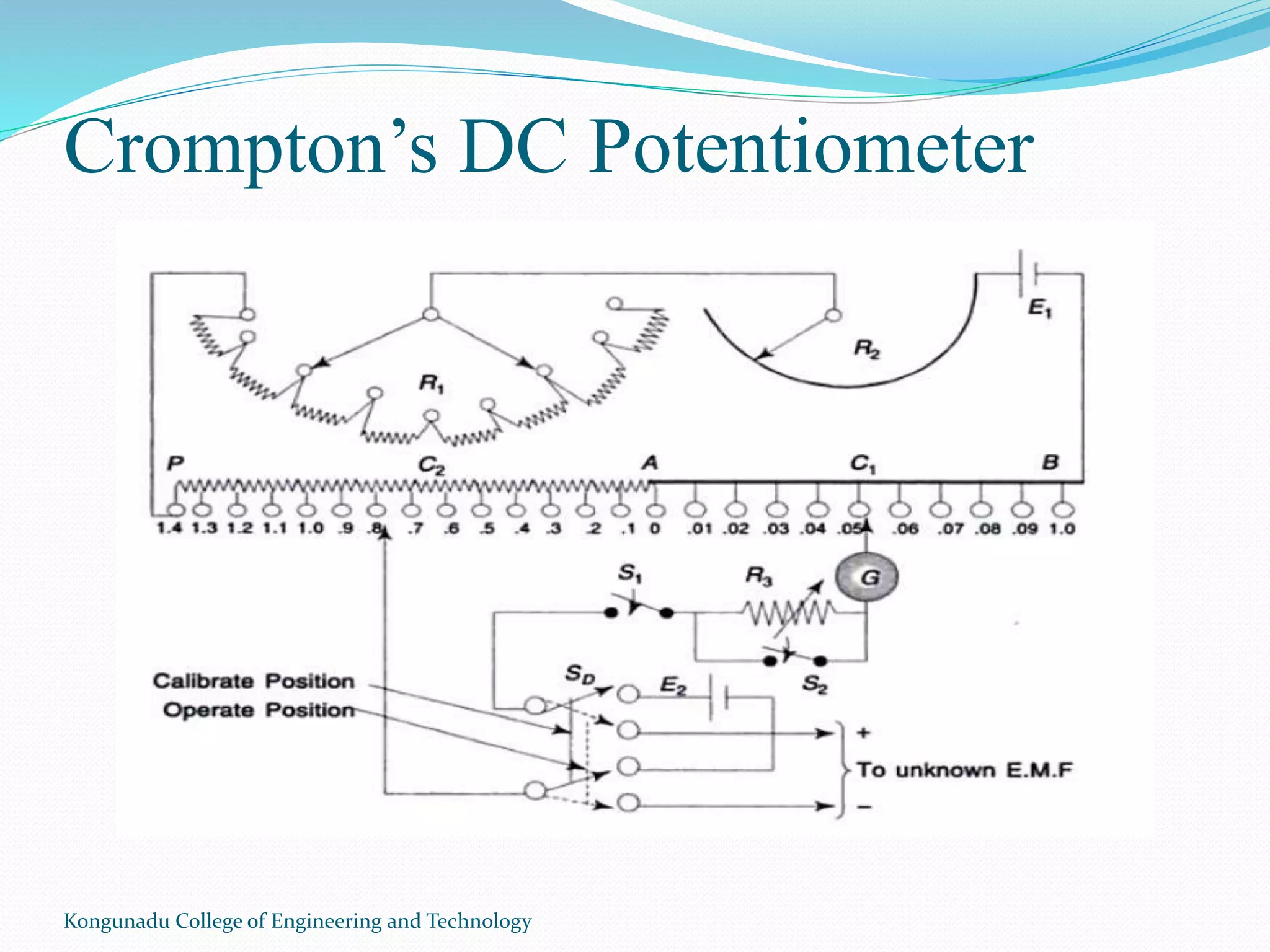
AB- graduatedslide wire having resistance 10Ω
PA- resistance coils each having resistance of slide wire
C1- slide moving over PA
C2- slide moving over AB
R1- coarse adjustment
R2- fine adjustment
E1- supply voltage
SD- double throw switch used to toggle betwenn
standardization and measurement of unknown emf
S1,S2- single throw switch
G- galvanometer
E2- standard cell used for standardization
Kongunadu College of Engineering and Technology
10.
Cont…
Standardization:
Galvanometer isheavily shunted
Potentiometer is stanrdized by putting SD switch in calibrate
position
For this Wetson type standard cell (1.0183V) is used
For this slide C2 is set on stud 1 and C1 is set on .0183
Now R1 and R2 are adjusted to get zero deflection on the
galvanometer
Kongunadu College of Engineering and Technology
11.
Cont…
Measurement of unknownemf
Switch S2 is closed
SD is kept at operate position
R1 and R2 is kept fixed as in standardized position
Now unknown emf is connected to SD
Slide contacts C1 and C2 are adjusted to obtain balance of the
potentiometer
At balance reading of the potentiometer directly gives the value
of unknown emf
Kongunadu College of Engineering and Technology
12.
Cont…
It isnot possible to arrange sliding contacts C1 and C2 to
coincide to exact reading
Before making measurement current has to be allowed to
flow through the potentiometer.
If balancing takes longer, then standardization has to be
checked
Standardization has to be checked each time while
measuring unknown emf.
Kongunadu College of Engineering and Technology
13.
What is Bridgecircuit?
A bridge circuit is a type of electrical circuit in which two
circuit branches (usually in parallel with each other) are
"bridged" by a third branch connected between the first two
branches at some intermediate point along them.
The bridge was originally developed for laboratory
measurement purposes and one of the intermediate bridging
points is often adjustable when so used.
Bridge circuits now find many applications, both linear and
non-linear, including in instrumentation, filtering and power
conversion.
Kongunadu College of Engineering and Technology
14.
BRIDGE CIRCUITS
DC Bridges
Wheatstone’s bridge
Kelvin’s Double Bridge
PO box
AC Bridges
Maxwell’s bridge
Scherig Bridge
Anderson Bridge
Wien’s Bridge
Kongunadu College of Engineering and Technology
Cont…
The bridgeis in balance condition when no current flows
through the coil or the potential difference across the
galvanometer is zero. This condition occurs when the potential
difference across the a to b and a to d are equal, and the
potential differences across the b to c and c to d remain same.
The current enters into the galvanometer divides into I1 and I2,
and their magnitude remains same. The following condition
exists when the current through the galvanometer is zero.
Kongunadu College of Engineering and Technology
Kelvin Bridge
TheKelvin bridge or Thompson bridge is used for
measuring the unknown resistances having a value less
than 1Ω. It is the modified form of the Wheatstone Bridge.
Wheatstone bridge use for measuring the resistance from a
few ohms to several kilo-ohms. But error occurs in the
result when it is used for measuring the low
resistance. This is the reason because of which
the Wheatstone bridge is modified, and the Kelvin bridge
obtains. The Kelvin bridge is suitable for measuring the
low resistance.
Kongunadu College of Engineering and Technology
20.
Cont…
The ris the resistance of the contacts that connect
the unknown resistance R to the standard resistance S.
The ‘m’ and ‘n’ show the range between which
the galvanometer is connected for obtaining a null point.
When the galvanometer is connected to point ‘m’, the lead
resistance r is added to the standard resistance S. Thereby the
very low indication obtains for unknown resistance R.
And if the galvanometer is connected to point n then the r adds
to the R, and hence the high value of unknown resistance is
obtained. Thus, at point n and m either very high or very low
value of unknown resistance is obtained.
Kongunadu College of Engineering and Technology
AC Bridges(Maxwell’s Bridge)
Maxwell’s bridge is an AC bridge having four arms, which are
connected in the form of a rhombus or square shape.
Two arms of this bridge consist of a single resistor, one arm
consists of a series combination of resistor and inductor & the
other arm consists of a parallel combination of resistor and
capacitor.
An AC detector and AC voltage source are used to find the
value of unknown impedance. Hence, one of these two are
placed in one diagonal of Maxwell’s bridge and the other one is
placed in other diagonal of Maxwell’s bridge.
Kongunadu College of Engineering and Technology
Hay’s Bridge
Kongunadu Collegeof Engineering and Technology
Hay’s bridge is a modified version of Maxwell’s bridge, which
we get by modifying the arm, which consists of a parallel
combination of resistor and capacitor into the arm, which
consists of a series combination of resistor and capacitor in
Maxwell’s bridge.
Hay’s bridge is used to measure the value of high inductance.
The circuit diagram of Hay’s bridge is shown in the below
figure.
Transformer Ratio Bridges
KongunaduCollege of Engineering and Technology
The transformer Ratio Bridges are becoming
increasingly popular and are being used for a wide range
of applications.This is on account of versatility and
accuracy of Ratio Transformers, which are used in
the transformer ratio bridges.
In fact, transformer ratio bridgesare replacing the
conventional ac bridges at a rapid rate.In this, we will
discuss transformer ratio bridge working principle.
A transformer ratio bridge consists of
voltage transformer whose performance approaches that of
an ideal transformer.An ideal transformer is one that has
no resistance, no core loss and no leakage flux
32.
Cont…
Kongunadu College ofEngineering and Technology
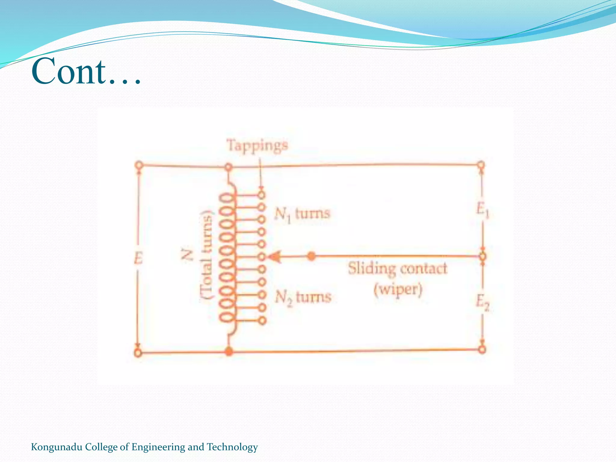
The below figure shows an autotransformer provided with
tappings. Suppose an alternating voltage E is applied across the
winding.Assuming that the autotransformer is ideal type, the
division of applied voltage E into output voltages E1 and E2 is
E1 = E. N1/N and E2 = E. N2/N
Different values of E1 and E2 may be had by changing the
position of the wiper on the tappings.
The magnetizing current is reduced by using a Toroidal
Core.The added advantage of a toroidal core is that winding put
on it has minimum leakage reactance giving an almost perfect
coupling.The leakage reactance can be reduced further by using
a special type of construction for the windings as shown in the
below figure of transformer ratio bridges.
Electrostatic and Electromagnetic
Interference
KongunaduCollege of Engineering and Technology
ELECTROMAGNETIC INTERFERENCE:
Electromagnetic interference (EMI), also called radio-
frequency interference (RFI) when in the radio
frequency spectrum, is a disturbance generated by an external
source that affects an electrical circuit by electromagnetic
induction, electrostatic coupling, or conduction.[1] The
disturbance may degrade the performance of the circuit or even
stop it from functioning. In the case of a data path, these effects
can range from an increase in error rate to a total loss of the
data.
INTERFERENCE BY RADIATION:
Interference by electromagnetic radiation becomes
important at cable lengths greater than 1/7 of the
wavelength of the signals. At frequencies beyond 30Mhz,
most of the interference occurs by e.m. radiation
35.
Cont…
Kongunadu College ofEngineering and Technology
Electro static Interference
Answer Electrostatics is the branch of physics which deals with
the study of electric charges at rest, that is, charged particles
that are stationary. Electrostatics is an area of physics . It
encompasses the study and analysis of electricity, its properties
and its applications
Charged persons and objects can store electrical charges of up
to several micro- Coulombs, which means voltages of some
10kV in respect to ground. Dry air, artificial fabrics and friction
favour these conditions.When touching grounded equipment,
an instantaneous discharge produces arcing with short, high
current pulses and associated strong changes of the e.m. field.
36.
INTRODUCTION
Kongunadu College ofEngineering and Technology
Everyelectronic device isa source of radiated electromagnetic
fieldscalled radiated emissions. Theseare often an accidental
by product of the design. An electromagnetic disturbance can
be electromagnetic noise, an unwanted signalora change in
the Propagation medium itself.
EMI: Electromagnetic interference is the degradation in the
performanceof a device or equipment or a system
RFI: Radio frequency interference is the degradation in the
reception of a wanted signal caused by radio frequency
disturbance
EMC: An electronic system that is able to function compatibly
with other electronic systems and not produce or be
susceptible to interference
37.
Electronic equipment issubjected to a variety of
electromagnetic interference sources. Careful design is
required to guarantee compatibility with environment-
Intersystem EMI
Kongunadu College of Engineering and Technology
38.
EXAMPLESOFEMI
Kongunadu College ofEngineering and Technology
TRANSMISSION LINES
MAINS POWER SUPPLY
SWITCHES AND RELAYS
TELEPHONE EQUIPMENT
AIRCRAFT NAVIGATION
BIOLOGICAL EFFECTS
MILITARY EQUIPMENT
INSECURE COMMUNICATIONS
INTEGRATED CIRCUITS
RADIO ASTRONOMY
EMI CONTROLING TECHNICS
KongunaduCollege of Engineering and Technology
• The source of EMI can be classified as natural or artificial (man-
made).
• The origin of EMI basically undesired conducted emissions
(voltage and/or currents) or radiated emissions (electrical and/or
magnetic fields).
• Conducted emissions are currents that are carried by metallic
paths (the unit’s power cord) and place on the common power
network, where they may cause interference with other devices
that are connected to the network.
• Both intrasystem and intersystem EMI can be controlled by
following some design guidelines and techniques.
41.
Cont…
Kongunadu College ofEngineering and Technology
1. coupling
2. Grounding or wiring
3. Shielding
4. Filtering
42.
Grounding:
Kongunadu College ofEngineering and Technology
• Grounding isthe establishmentof an electricallyconductive path
between two pointsto connect electric and electronic elements
of a systemto one another orto some reference point which is
designated asground.
• An ideal ground plane have a zeroimpedance and zeropotential
that
can be used as reference point for all signalsinassociated circuitry.
• Thepurpose of the floatingground isto isolateelements or
circuitsfroma common groundplane
• Bonding isthe the establishmentof a low impedance path
between two metal surfaces
• Thepurpose of a bond to make a structurehomogeneouslywith
respect to the flow of electrical currents thusavoiding the
development of potentials between the metallicparts,since such
43.
Cont…
Kongunadu College ofEngineering and Technology
• Thepurpose of a bond to make a structurehomogeneouslywith
respect to the flow of electrical currentsthusavoiding the
development of potentials between the metallicparts,since such
potentialsmay resultsinEMI.
44.
Shielding
Kongunadu College ofEngineering and Technology
• Electromagnetic shielding is the practice of reducing the
electromagnetic fields in a space by
blocking the field with barriers made of conductive or
magnetic materials.
• Shielding is typically applied to enclosures to isolate electrical
devices from the 'outside world', and to cables to isolate wires
from the environment through which the cable runs.
Electromagnetic shielding that blocks radio frequency
electromagnetic radiation is also known as RF shielding.
• The shielding can reduce the coupling of radio waves ,
electromagnetic fields and electrostatic fields.
• A conductive enclosure used to block electrostatic fields is also
known as a Faraday cage.
• The amount of reduction depends very much upon the
45.
Cont…
Kongunadu College ofEngineering and Technology
• A conductive enclosure used to block electrostatic fields is also
known as a Faraday cage.
• The amount of reduction depends very much upon the
material used, its thickness, the size of the shielded volume
and the frequency of the fields of interest and the size, shape
and orientation of apertures in a shield to an incident
electromagneticfield.


![Electrostatic and Electromagnetic
Interference
Kongunadu College of Engineering and Technology
ELECTROMAGNETIC INTERFERENCE:
Electromagnetic interference (EMI), also called radio-
frequency interference (RFI) when in the radio
frequency spectrum, is a disturbance generated by an external
source that affects an electrical circuit by electromagnetic
induction, electrostatic coupling, or conduction.[1] The
disturbance may degrade the performance of the circuit or even
stop it from functioning. In the case of a data path, these effects
can range from an increase in error rate to a total loss of the
data.
INTERFERENCE BY RADIATION:
Interference by electromagnetic radiation becomes
important at cable lengths greater than 1/7 of the
wavelength of the signals. At frequencies beyond 30Mhz,
most of the interference occurs by e.m. radiation](https://image.slidesharecdn.com/unit3-190120155212/75/Unit-3-34-2048.jpg)