Download to read offline

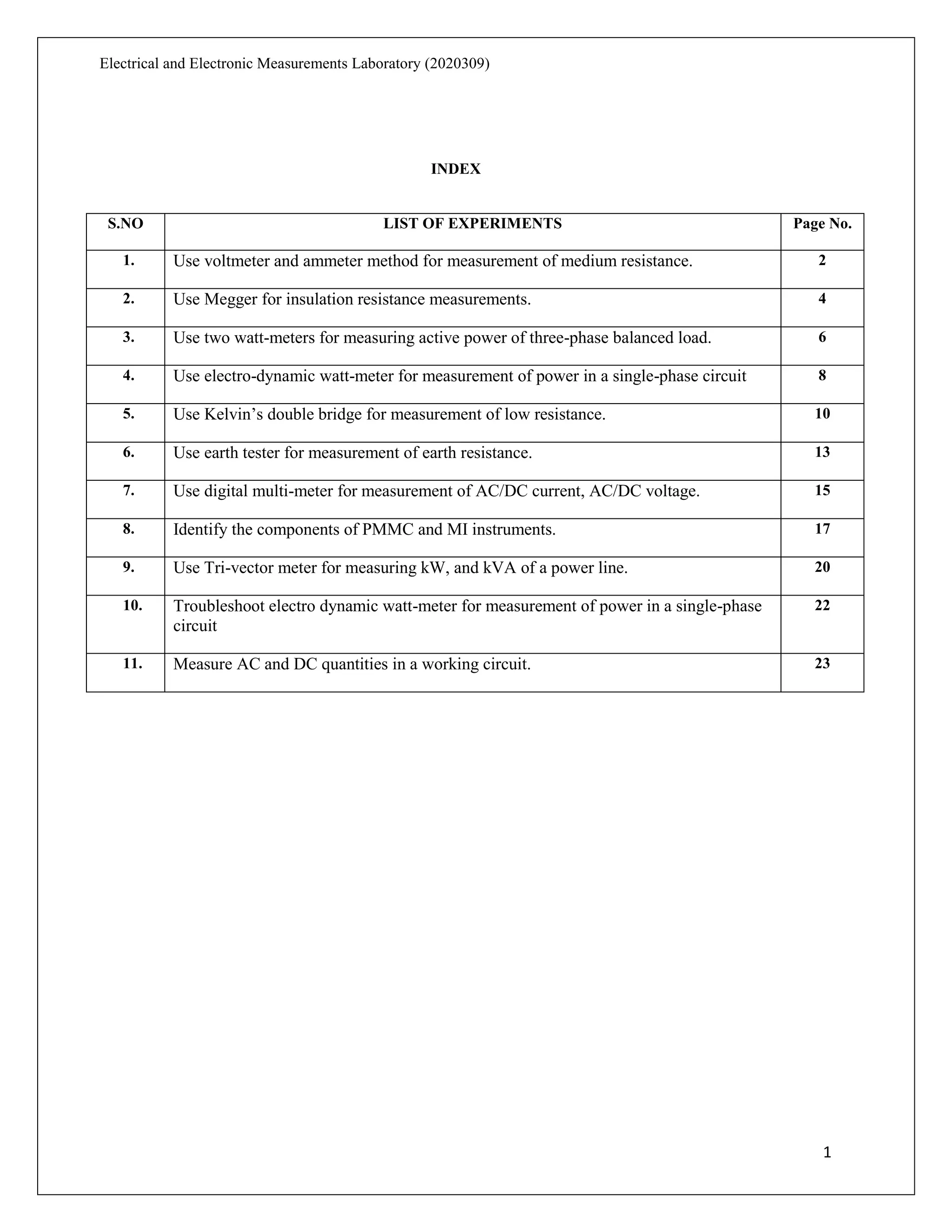
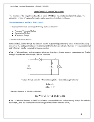
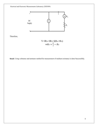
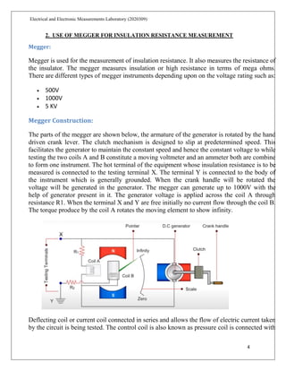
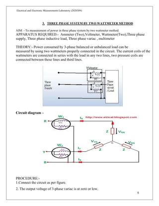
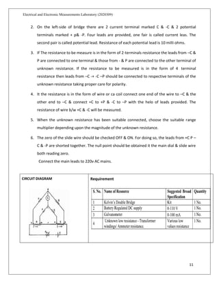

This document provides instructions for experiments to be conducted in an electrical and electronic measurements laboratory. It includes 12 experiments such as using various meters and bridges to measure resistance, insulation resistance, power, power factor, and calibrating instruments. Specific experiments include using a voltmeter and ammeter to measure medium resistances, using a Megger to measure insulation resistance, using two wattmeters to measure power in a three-phase system, and using Kelvin's double bridge to measure low resistances. Procedures and connections for each experiment are described.