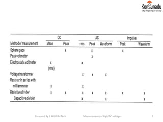
This document discusses several methods for measuring high DC voltages:
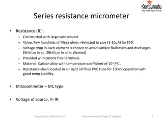
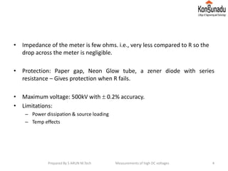
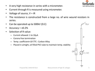
1. Series resistance micrometers measure voltage by passing a known small current through a high-value resistor and measuring the voltage drop, allowing measurement up to 500kV.
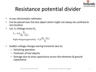
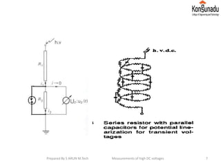
2. Resistance potential dividers use two high-value resistors to proportionally step down a high voltage to a measurable level.
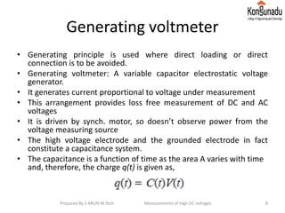
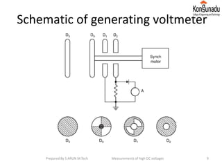
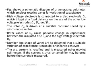
3. Generating voltmeters induce a small current proportional to the measured voltage without a direct connection.
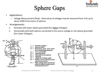
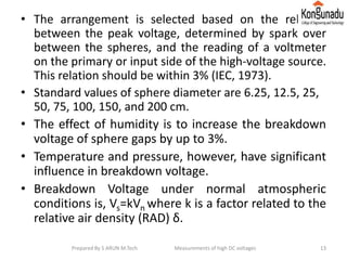
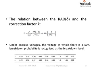
4. Sphere gaps measure peak voltages up to 2500kV by measuring the sparkover voltage between two conductive spheres. Atmospheric conditions and spacing accuracy affect measurements.