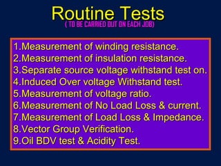
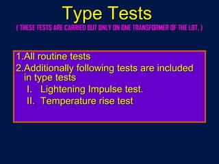
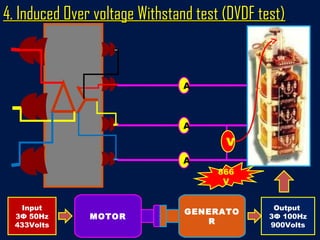
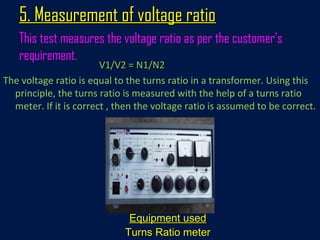
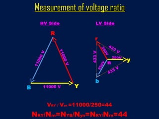
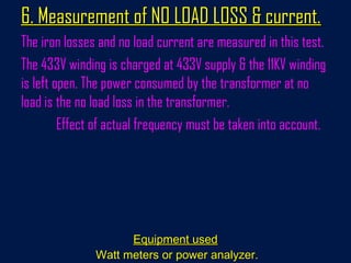
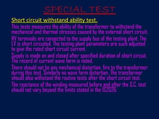
Testing Of DistributionTesting Of Distribution
TransformerTransformer
ByBy
R. MondalR. Mondal
SE & Project Manager, W.B.S.E.D.C.L.SE & Project Manager, W.B.S.E.D.C.L.
Certified Energy Manager & Certified Energy Auditor
AtAt
EETI, KolkataEETI, Kolkata
WBSEDCLWBSEDCL
Transformer Testing As Per IS-2026Transformer Testing As Per IS-2026
1.1.Measurement of winding resistance.Measurement of winding resistance.
2.2.Measurement of insulation resistance.Measurement of insulation resistance.
3.3.Separate source voltage withstand test on.Separate source voltage withstand test on.
4.4.Induced Over voltage Withstand test.Induced Over voltage Withstand test.
5.5.Measurement of voltage ratio.Measurement of voltage ratio.
6.6.Measurement of No Load Loss & current.Measurement of No Load Loss & current.
7.7.Measurement of Load Loss & Impedance.Measurement of Load Loss & Impedance.
8.8.Vector Group Verification.Vector Group Verification.
9.9.Oil BDV test & Acidity Test.Oil BDV test & Acidity Test.
Routine TestsRoutine Tests( TO BE CARRIED OUT ON EACH JOB)( TO BE CARRIED OUT ON EACH JOB)
Type TestsType Tests
1.1.All routine testsAll routine tests
2.2.Additionally following tests are includedAdditionally following tests are included
in type testsin type tests
I.I. Lightening Impulse test.Lightening Impulse test.
II.II. Temperature rise testTemperature rise test
( THESE TESTS ARE CARRIED OUT ONLY ON ONE TRANSFORMER OF THE LOT. )( THESE TESTS ARE CARRIED OUT ONLY ON ONE TRANSFORMER OF THE LOT. )
Special TestsSpecial Tests
1.1.Additional Impulse test.Additional Impulse test.
2.2.Short circuit test.Short circuit test.
3.3.Measurement of zero Phase sequenceMeasurement of zero Phase sequence
Impedance test.Impedance test.
4.4.Measurement of acoustic noise level.Measurement of acoustic noise level.
5.5.Measurement of harmonics of the no loadMeasurement of harmonics of the no load
current.current.
6.6.Magnetic balance test.Magnetic balance test.
Routine TestsRoutine Tests
1. Measurement of winding resistance1. Measurement of winding resistance
Equipment usedEquipment used
Digital resistance meterDigital resistance meter
This test measures the resistance of the HV & LV winding.
The values of resistance should be balance for all three
phases and should match the designed values.
2. Measurement of insulation resistance. Measurement of insulation resistance
Equipment usedEquipment used
INSULATION TESTER OR MEGGERINSULATION TESTER OR MEGGER
Recommended Values are 2000 Mohms for HV & 500 Mohms for LV.
Measures the insulation resistance of HV & LV windings with
respect to earth (body) and between LV & HV winding.
3. Separate source voltage withstand test3. Separate source voltage withstand test
(High Voltage tests on HV & LV)(High Voltage tests on HV & LV)
HV high voltage testHV high voltage test :: LV winding connected togetherLV winding connected together
and earthed. HV winding connected together and givenand earthed. HV winding connected together and given
28 KV (21 KV for repaired DTRs.) for 1 minute.28 KV (21 KV for repaired DTRs.) for 1 minute.
LV high Voltage testLV high Voltage test :: HV winding connected togetherHV winding connected together
and earthed. LV winding connected together and givenand earthed. LV winding connected together and given
3 KV (2.25 KV for repaired DTRs.) for 1 minute.3 KV (2.25 KV for repaired DTRs.) for 1 minute.
Equipment usedEquipment used
High Voltage tester (High Voltage tester ( 100100 KV &KV & 33 KV)KV)
This test checks the insulation property between Primary to
earth, Secondary to earth and between Primary &
Secondary.
A
V
1Φ
230V
28K
V
Separate source voltage withstand test HV SideSeparate source voltage withstand test HV Side
A
V
1Φ
230V
Separate source voltage withstand test LV SideSeparate source voltage withstand test LV Side
3KV
4. Induced Over voltage Withstand test (DVDF test)4. Induced Over voltage Withstand test (DVDF test)
This test checks the inter turn insulation.
For a 11KV/433V transformer,866 Volts are applied at the
433V winding with the help of a Generator for 1 minute.
This induces 22KV on 11KV side. The frequency of the
866V supply is also increased to 100HZ.
Equipment usedEquipment used
MOTOR GENERATOR SETMOTOR GENERATOR SET
A
A
V
4. Induced Over voltage Withstand test (DVDF test)4. Induced Over voltage Withstand test (DVDF test)
A
MOTOR
GENERATO
R
Input
3Φ 50Hz
433Volts
Output
3Φ 100Hz
900Volts
866
V
5. Measurement of voltage ratio5. Measurement of voltage ratio
This test measures the voltage ratio as per the customer’s
requirement.
V1/V2 = N1/N2V1/V2 = N1/N2
The voltage ratio is equal to the turns ratio in a transformer. Using this
principle, the turns ratio is measured with the help of a turns ratio
meter. If it is correct , then the voltage ratio is assumed to be correct.
Equipment usedEquipment used
Turns Ratio meterTurns Ratio meter
HV Side LV Side
R
YB
r
y
b
11000V
433V
11000 V
11000V
433 V
433
V
250V
250V
250V
VRY / Vrn =11000/250=44
NRY/Nrn=NYB/Nyn=NRY/Nrn=44
n
Measurement of voltage ratioMeasurement of voltage ratio
6. Measurement of NO LOAD LOSS & current.6. Measurement of NO LOAD LOSS & current.
The iron losses and no load current are measured in this test.
The 433V winding is charged at 433V supply & the 11KV winding
is left open. The power consumed by the transformer at no
load is the no load loss in the transformer.
Effect of actual frequency must be taken into account.
Equipment usedEquipment used
Watt meters or power analyzer.Watt meters or power analyzer.
A
AW
W
Measurement of NO LOAD LOSS & CurrentMeasurement of NO LOAD LOSS & Current
V
433
V
7.Measurement of LOAD LOSS & IMPEDENCE.7.Measurement of LOAD LOSS & IMPEDENCE.
(EFFICIENCY & REGULATION)(EFFICIENCY & REGULATION)
This test measures the power consumed by the transformer when
the 433V winding is short circuited and The rated current is passed
through the 11KV winding.
Equipment used :Equipment used :
Wattmeters or power analyzer.Wattmeters or power analyzer.
A
A W
W
V
7.Measurement of LOAD LOSS & IMPEDENCE7.Measurement of LOAD LOSS & IMPEDENCE
Rated
Curren
t
8. Vector Group Verification test8. Vector Group Verification test
This test verifies the Dyn-11 vector group of a distribution
transformer.
Equipment usedEquipment used
voltmeter.voltmeter.
Supply,3,50Hz,433Volts
HV
Sid
e
LV
Sid
e
R
YB
r
y
b
n
VRY=VRn+VnY
VYb=VYy
Vby>VBb
Vector Group Verification testVector Group Verification test
9. Oil BDV test & Acidity Test.9. Oil BDV test & Acidity Test.
Oil breakdown voltage is checked as per IS-335.
100 mm L X 70 mm B X 80 mm Ht. glass pot. 500ml Oil sample.
Spherical electrodes with gap of 2.5 mm, Recommended value : 40KV
Acidity Of Oil Recommended value : 0.5 mg KOH / gm of Oil.
Equipment used
OIL BDV TEST SET & Acidity Testing Kits.OIL BDV TEST SET & Acidity Testing Kits.
Type TestsType Tests
LIGHTENING IMPULSE TESTLIGHTENING IMPULSE TEST
All the dielectric tests check the insulation level of the job.
Impulse generator is used to produce the specified voltage impulse wave
of 1.2/50 micro seconds wave
One impulse of a reduced voltage between 50 to 75% of the full test
voltage and subsequent three impulses at full voltage.
For a three phase transformer, impulse is carried out on all three phases
in succession.
The voltage is applied on each of the line terminal in succession, keeping
the other terminals earthed.
The current and voltage wave shapes are recorded on the oscilloscope
and any distortion in the wave shape is the criteria for failure.
SPECIAL TEST
Short circuit withstand ability test.Short circuit withstand ability test.
This tests measures the ability of the transformer to withstand the
mechanical and thermal stresses caused by the external short circuit.
HV terminals are connected to the supply bus of the testing plant. The
LV is short circuited. The testing plant parameters are such adjusted
to give the rated short circuit current.
Supply is made on and closed after specified duration of short circuit.
The record of current wave form is noted.
There should not be any mechanical distortion, fire to the transformer
during this test. Similarly no wave form distortion. The transformer
should also withstand the routine tests after the short circuit test.
The reactance of the winding measured before and after the S.C. test
should not vary beyond the limits stated in the IS2026.
Distribution Transformer testing,  West Bengal, India

Distribution Transformer testing, West Bengal, India

  • 1.
    Testing Of DistributionTestingOf Distribution TransformerTransformer ByBy R. MondalR. Mondal SE & Project Manager, W.B.S.E.D.C.L.SE & Project Manager, W.B.S.E.D.C.L. Certified Energy Manager & Certified Energy Auditor AtAt EETI, KolkataEETI, Kolkata WBSEDCLWBSEDCL
  • 2.
    Transformer Testing AsPer IS-2026Transformer Testing As Per IS-2026
  • 3.
    1.1.Measurement of windingresistance.Measurement of winding resistance. 2.2.Measurement of insulation resistance.Measurement of insulation resistance. 3.3.Separate source voltage withstand test on.Separate source voltage withstand test on. 4.4.Induced Over voltage Withstand test.Induced Over voltage Withstand test. 5.5.Measurement of voltage ratio.Measurement of voltage ratio. 6.6.Measurement of No Load Loss & current.Measurement of No Load Loss & current. 7.7.Measurement of Load Loss & Impedance.Measurement of Load Loss & Impedance. 8.8.Vector Group Verification.Vector Group Verification. 9.9.Oil BDV test & Acidity Test.Oil BDV test & Acidity Test. Routine TestsRoutine Tests( TO BE CARRIED OUT ON EACH JOB)( TO BE CARRIED OUT ON EACH JOB)
  • 4.
    Type TestsType Tests 1.1.Allroutine testsAll routine tests 2.2.Additionally following tests are includedAdditionally following tests are included in type testsin type tests I.I. Lightening Impulse test.Lightening Impulse test. II.II. Temperature rise testTemperature rise test ( THESE TESTS ARE CARRIED OUT ONLY ON ONE TRANSFORMER OF THE LOT. )( THESE TESTS ARE CARRIED OUT ONLY ON ONE TRANSFORMER OF THE LOT. )
  • 5.
    Special TestsSpecial Tests 1.1.AdditionalImpulse test.Additional Impulse test. 2.2.Short circuit test.Short circuit test. 3.3.Measurement of zero Phase sequenceMeasurement of zero Phase sequence Impedance test.Impedance test. 4.4.Measurement of acoustic noise level.Measurement of acoustic noise level. 5.5.Measurement of harmonics of the no loadMeasurement of harmonics of the no load current.current. 6.6.Magnetic balance test.Magnetic balance test.
  • 6.
  • 7.
    1. Measurement ofwinding resistance1. Measurement of winding resistance Equipment usedEquipment used Digital resistance meterDigital resistance meter This test measures the resistance of the HV & LV winding. The values of resistance should be balance for all three phases and should match the designed values.
  • 8.
    2. Measurement ofinsulation resistance. Measurement of insulation resistance Equipment usedEquipment used INSULATION TESTER OR MEGGERINSULATION TESTER OR MEGGER Recommended Values are 2000 Mohms for HV & 500 Mohms for LV. Measures the insulation resistance of HV & LV windings with respect to earth (body) and between LV & HV winding.
  • 9.
    3. Separate sourcevoltage withstand test3. Separate source voltage withstand test (High Voltage tests on HV & LV)(High Voltage tests on HV & LV) HV high voltage testHV high voltage test :: LV winding connected togetherLV winding connected together and earthed. HV winding connected together and givenand earthed. HV winding connected together and given 28 KV (21 KV for repaired DTRs.) for 1 minute.28 KV (21 KV for repaired DTRs.) for 1 minute. LV high Voltage testLV high Voltage test :: HV winding connected togetherHV winding connected together and earthed. LV winding connected together and givenand earthed. LV winding connected together and given 3 KV (2.25 KV for repaired DTRs.) for 1 minute.3 KV (2.25 KV for repaired DTRs.) for 1 minute. Equipment usedEquipment used High Voltage tester (High Voltage tester ( 100100 KV &KV & 33 KV)KV) This test checks the insulation property between Primary to earth, Secondary to earth and between Primary & Secondary.
  • 10.
    A V 1Φ 230V 28K V Separate source voltagewithstand test HV SideSeparate source voltage withstand test HV Side
  • 11.
    A V 1Φ 230V Separate source voltagewithstand test LV SideSeparate source voltage withstand test LV Side 3KV
  • 12.
    4. Induced Overvoltage Withstand test (DVDF test)4. Induced Over voltage Withstand test (DVDF test) This test checks the inter turn insulation. For a 11KV/433V transformer,866 Volts are applied at the 433V winding with the help of a Generator for 1 minute. This induces 22KV on 11KV side. The frequency of the 866V supply is also increased to 100HZ. Equipment usedEquipment used MOTOR GENERATOR SETMOTOR GENERATOR SET
  • 13.
    A A V 4. Induced Overvoltage Withstand test (DVDF test)4. Induced Over voltage Withstand test (DVDF test) A MOTOR GENERATO R Input 3Φ 50Hz 433Volts Output 3Φ 100Hz 900Volts 866 V
  • 14.
    5. Measurement ofvoltage ratio5. Measurement of voltage ratio This test measures the voltage ratio as per the customer’s requirement. V1/V2 = N1/N2V1/V2 = N1/N2 The voltage ratio is equal to the turns ratio in a transformer. Using this principle, the turns ratio is measured with the help of a turns ratio meter. If it is correct , then the voltage ratio is assumed to be correct. Equipment usedEquipment used Turns Ratio meterTurns Ratio meter
  • 15.
    HV Side LVSide R YB r y b 11000V 433V 11000 V 11000V 433 V 433 V 250V 250V 250V VRY / Vrn =11000/250=44 NRY/Nrn=NYB/Nyn=NRY/Nrn=44 n Measurement of voltage ratioMeasurement of voltage ratio
  • 16.
    6. Measurement ofNO LOAD LOSS & current.6. Measurement of NO LOAD LOSS & current. The iron losses and no load current are measured in this test. The 433V winding is charged at 433V supply & the 11KV winding is left open. The power consumed by the transformer at no load is the no load loss in the transformer. Effect of actual frequency must be taken into account. Equipment usedEquipment used Watt meters or power analyzer.Watt meters or power analyzer.
  • 17.
    A AW W Measurement of NOLOAD LOSS & CurrentMeasurement of NO LOAD LOSS & Current V 433 V
  • 18.
    7.Measurement of LOADLOSS & IMPEDENCE.7.Measurement of LOAD LOSS & IMPEDENCE. (EFFICIENCY & REGULATION)(EFFICIENCY & REGULATION) This test measures the power consumed by the transformer when the 433V winding is short circuited and The rated current is passed through the 11KV winding. Equipment used :Equipment used : Wattmeters or power analyzer.Wattmeters or power analyzer.
  • 19.
    A A W W V 7.Measurement ofLOAD LOSS & IMPEDENCE7.Measurement of LOAD LOSS & IMPEDENCE Rated Curren t
  • 20.
    8. Vector GroupVerification test8. Vector Group Verification test This test verifies the Dyn-11 vector group of a distribution transformer. Equipment usedEquipment used voltmeter.voltmeter.
  • 21.
  • 22.
    9. Oil BDVtest & Acidity Test.9. Oil BDV test & Acidity Test. Oil breakdown voltage is checked as per IS-335. 100 mm L X 70 mm B X 80 mm Ht. glass pot. 500ml Oil sample. Spherical electrodes with gap of 2.5 mm, Recommended value : 40KV Acidity Of Oil Recommended value : 0.5 mg KOH / gm of Oil. Equipment used OIL BDV TEST SET & Acidity Testing Kits.OIL BDV TEST SET & Acidity Testing Kits.
  • 23.
  • 24.
    LIGHTENING IMPULSE TESTLIGHTENINGIMPULSE TEST All the dielectric tests check the insulation level of the job. Impulse generator is used to produce the specified voltage impulse wave of 1.2/50 micro seconds wave One impulse of a reduced voltage between 50 to 75% of the full test voltage and subsequent three impulses at full voltage. For a three phase transformer, impulse is carried out on all three phases in succession. The voltage is applied on each of the line terminal in succession, keeping the other terminals earthed. The current and voltage wave shapes are recorded on the oscilloscope and any distortion in the wave shape is the criteria for failure.
  • 25.
    SPECIAL TEST Short circuitwithstand ability test.Short circuit withstand ability test. This tests measures the ability of the transformer to withstand the mechanical and thermal stresses caused by the external short circuit. HV terminals are connected to the supply bus of the testing plant. The LV is short circuited. The testing plant parameters are such adjusted to give the rated short circuit current. Supply is made on and closed after specified duration of short circuit. The record of current wave form is noted. There should not be any mechanical distortion, fire to the transformer during this test. Similarly no wave form distortion. The transformer should also withstand the routine tests after the short circuit test. The reactance of the winding measured before and after the S.C. test should not vary beyond the limits stated in the IS2026.