Downloaded 417 times

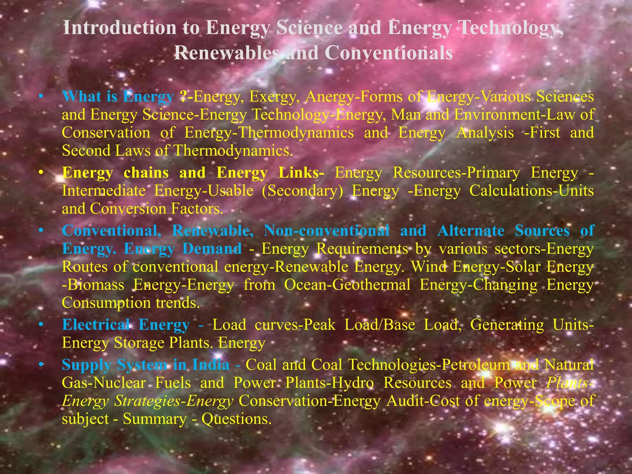


This document discusses renewable energy sources and provides an overview of energy science and technology. It covers various forms of energy, both renewable and non-renewable sources, energy transformations, energy demand trends, and the relationship between energy science and other fields like physics, chemistry, and biology. The increasing global demand for energy is driven by population growth, industrialization, and rising standards of living. While demand for energy is growing rapidly, renewable sources currently only provide a small portion of global energy but are expected to contribute a larger share in the coming decades.