Downloaded 165 times
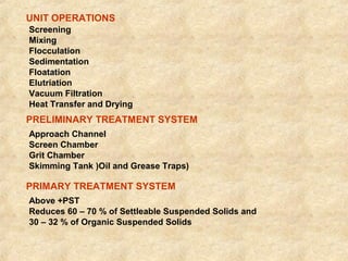
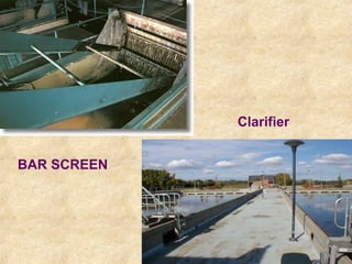
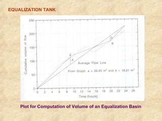
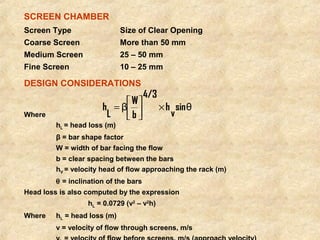
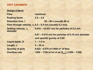
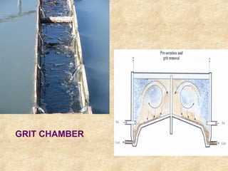
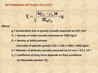
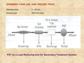
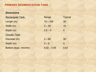
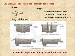
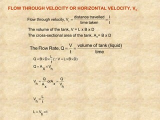
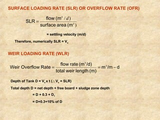


This document summarizes an expert lecture on unit operations for wastewater treatment. It discusses various unit treatment processes including screening, mixing, flocculation, sedimentation, and filtration. It provides details on the design considerations and criteria for preliminary treatment systems including channels, screens, grit chambers, and skimming tanks. The primary functions and design of bar screens, equalization tanks, screen chambers, grit chambers, and primary sedimentation tanks are also outlined. Settling velocities and loading rates for different treatment units are defined through mathematical equations.


