Downloaded 266 times

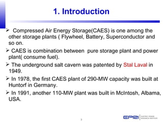
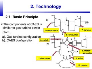
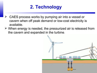
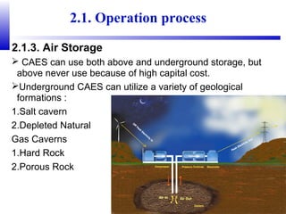

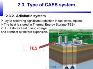
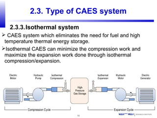

Compressed air energy storage (CAES) stores energy by using excess electricity to compress and pump air into underground storage facilities such as salt caverns. The stored air is later released to drive turbines and generate electricity during peak demand periods. There are three main types of CAES systems - diabatic, adiabatic, and isothermal. Diabatic systems are the most common and require natural gas combustion during discharge, while adiabatic and isothermal systems aim to reduce or eliminate fuel usage through heat recovery and storage techniques. CAES provides large-scale, low-cost energy storage and helps integrate renewable energy sources by storing excess power, but has disadvantages related to water contamination and salt waste from underground


