Downloaded 159 times
![the hydraulic retention time for CFSTR is given by
é ù
ê ú
ë û
t = 1 C o
-1
CFSTR
e
K C
for first order reaction
é ù
ê ú
ë û
and t = 1 C -C
0 e
CFSTR 2
e
K C
for second order reaction
é ù
ê ú
ë û
t = 1 C 0
-1
CFSTR
K C C
e e
where, K = second order rate constant, [(mg/L)xd]-1
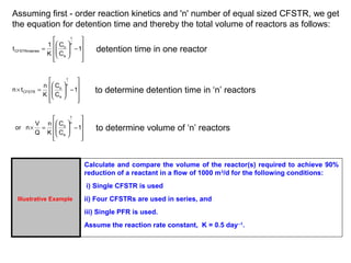
Illustrative Example
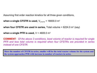
A wastewater is being treated in a CFSTR following first order reaction
kinetics with a reaction rate constant equal to 0.15 day-1. For a reactor
volume of 50 m3, what should be the flow rate to achieve 96% treatment
efficiency? For this flow rate, compute the reactor volume if the desired
treatment efficiency is 98%?
Flow rate of wastewater required to achieve 96% efficiency in CFSTR of 50 m3 capacity is 0.313
m3/day. Now, for same operating conditions, when the desired treatment efficiency of 98% is to
be achieved, the volume required will be 102.25 m3 .
Thus, the capacity of the reactor will be almost doubled (from 50 m3 to 102 m3) when
treatment efficiency is increased from 96% to 98% for the given conditions of wastewater
treatment.](https://image.slidesharecdn.com/reactorsitskinetics-140920141723-phpapp02/85/R-e-a-c-t-o-r-s-its-kinetics-6-320.jpg)
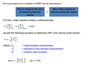
![i.e. - dc = dx (-ve sign implies a decrease in reactant concentration)
dt v
where, v = velocity of flow through reactor
dx = differential change in distance along the length of reactor
Integrating the left hand side of the equation between concentration limits C0 to Ce and
integrating right hand side of the equation for lengths zero to L and substituting the value of v/Q
for L/v; we get the equations to determine HRT and volume of reactor as given below:
For first order reaction kinetics,
é ù
ê o
ú
ë û
PFR
e
t = 1 lnC
K C
é ù
ê ú
ë û
V = Q lnC
o
e
K C
Similarly for second order reaction kinetics,
é ù
ê ú
ë û PFR
t = 1 1 - 1 for second order reaction
K C C
e 0
é ù
ê ú
ë û
t = 1 C 0
-1
PFR
K C C
0 e
where, K = second order rate constant, [(mg/L)xd]-1
é ù
ê ú
ë e 0 û
and V = Q 1 - 1 for second order reaction
K C C](https://image.slidesharecdn.com/reactorsitskinetics-140920141723-phpapp02/85/R-e-a-c-t-o-r-s-its-kinetics-8-320.jpg)
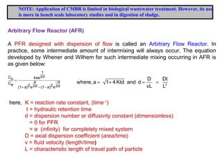
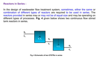
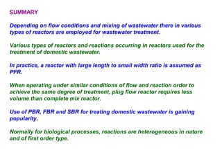


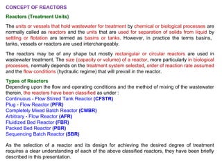
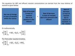
This document provides an overview of different types of reactors used in wastewater treatment processes. It defines reactors as vessels that hold wastewater for treatment and describes common reactor shapes. It then classifies and describes several reactor types including continuously stirred tank reactors, plug flow reactors, completely mixed batch reactors, fluidized bed reactors, packed bed reactors, and sequencing batch reactors. For each reactor type, diagrams are provided and equations are derived for hydraulic retention time and effluent concentrations based on reaction kinetics. Examples are also included to illustrate reactor sizing calculations.


