


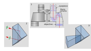
![2. Forms of prisms used in ophthalmic instruments.
As reflectors of light (with total internal reflection within the prism 1) right angled prism with
deviation 90°, 2) right angled prism with deviation 180° [Porro prism], 3) two right angled
prisms, 4) Dove prism](https://image.slidesharecdn.com/reflectionandrefractionathomesurfacescurved-150517032335-lva1-app6891/85/Reflection-and-refraction-at-home-curved-surfaces-34-320.jpg)


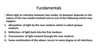
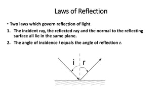
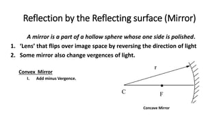
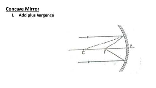
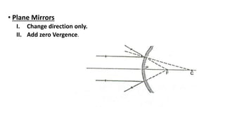
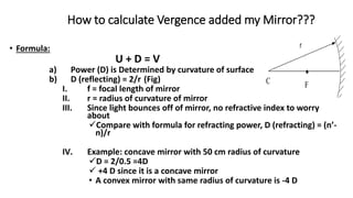
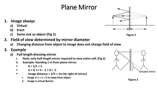
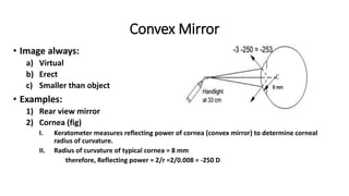
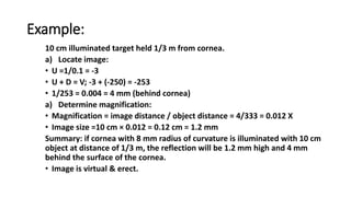
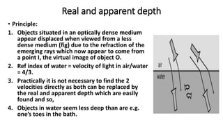
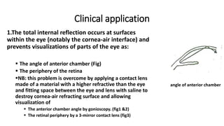
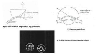
This document discusses reflection and refraction at surfaces and curved surfaces. It begins by explaining the fundamentals of reflection, refraction, and total internal reflection. It then discusses the laws of reflection and refraction. Specific examples of reflection and refraction are provided for plane mirrors, convex mirrors, concave mirrors, and refraction through lenses and the cornea. Clinical applications of reflection and refraction in the eye and optical instruments are described.