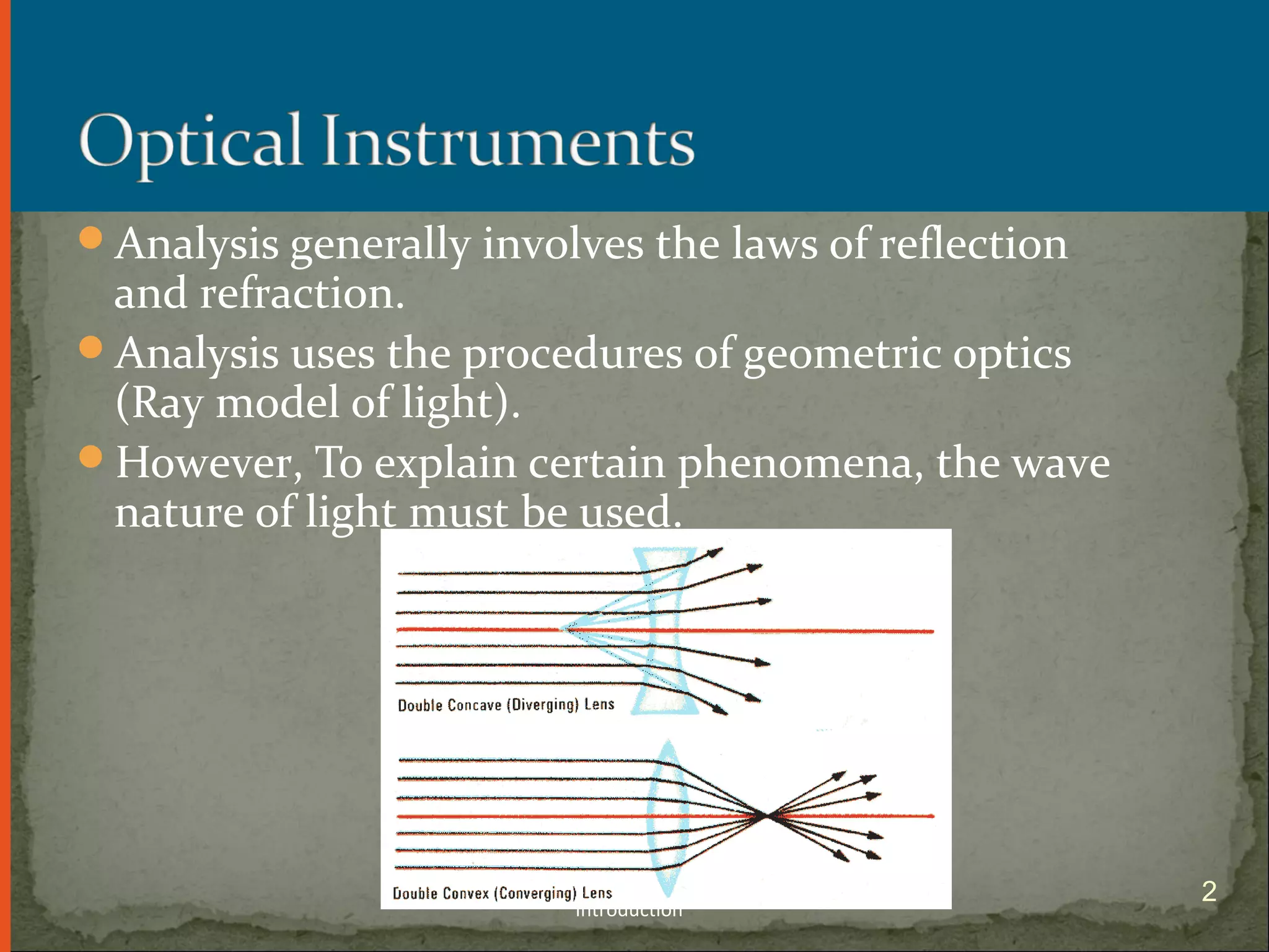
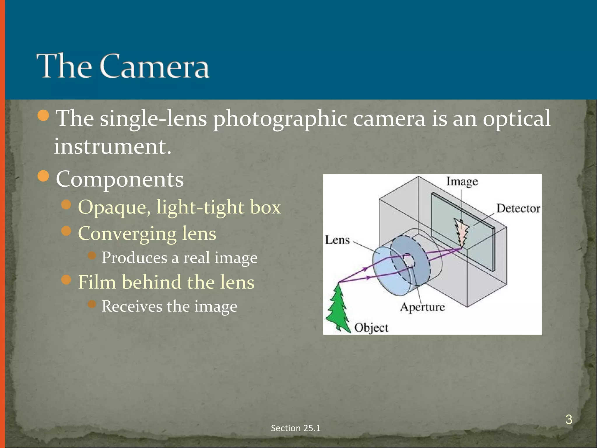
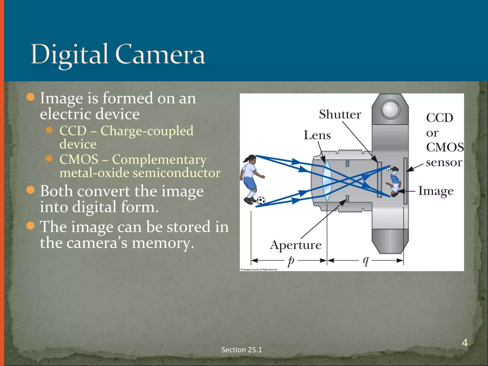
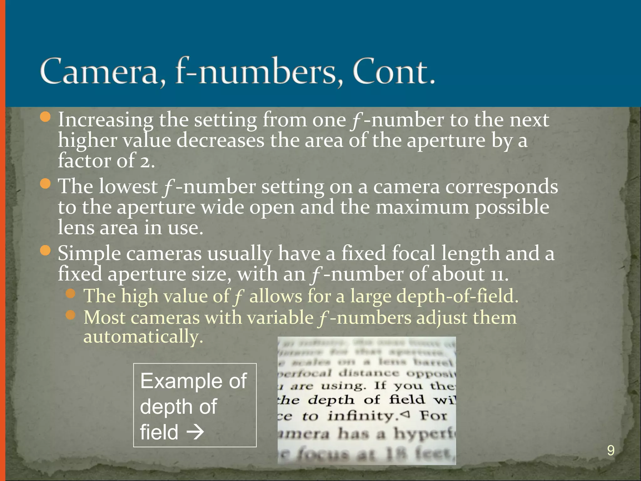
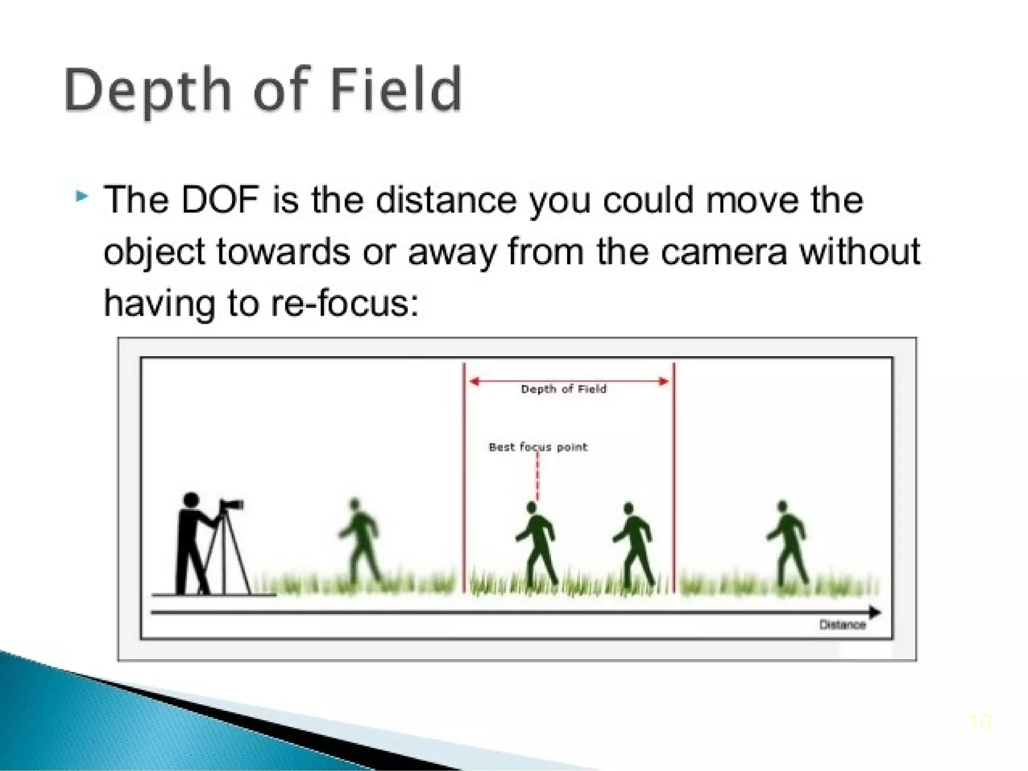
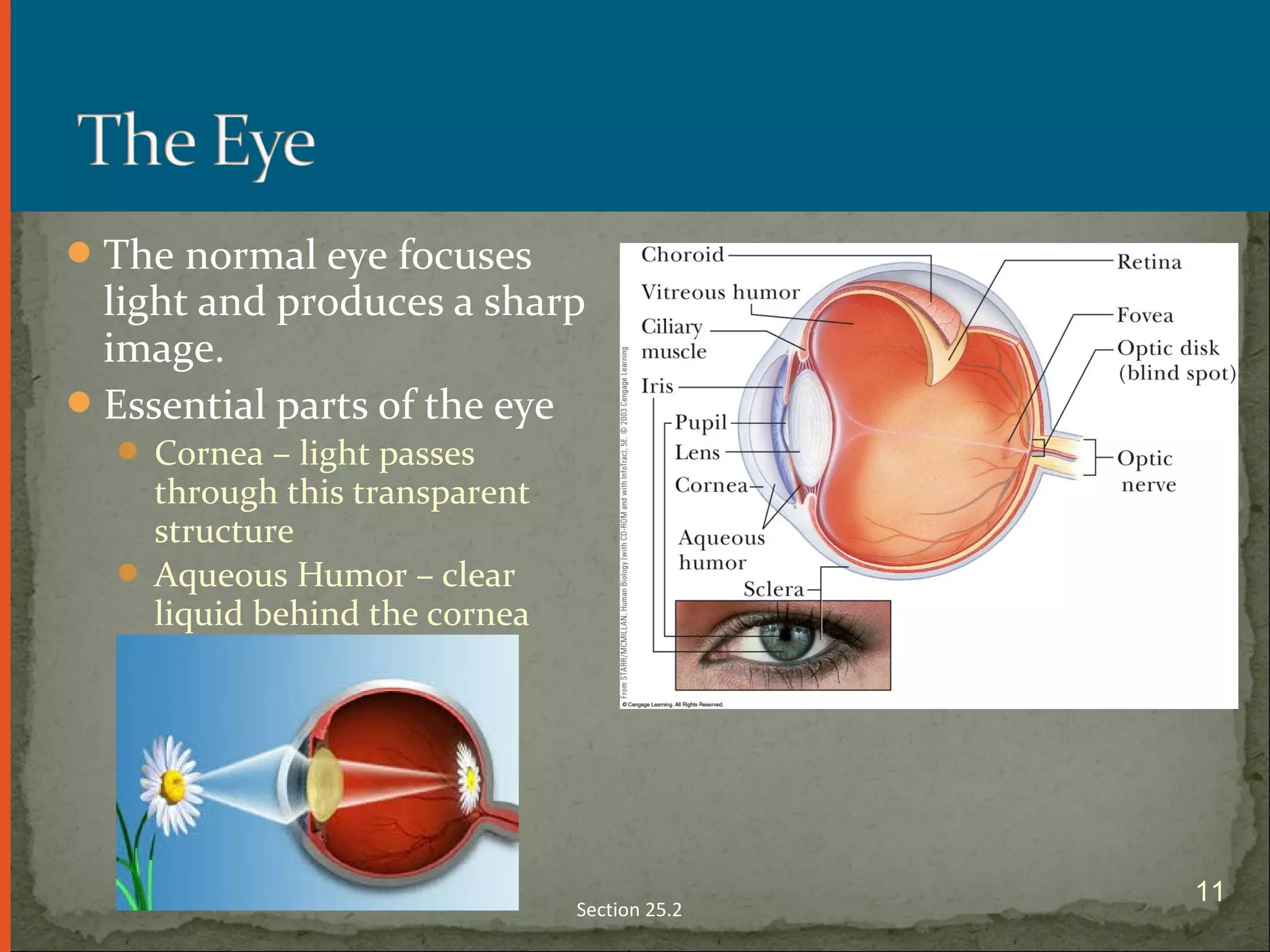
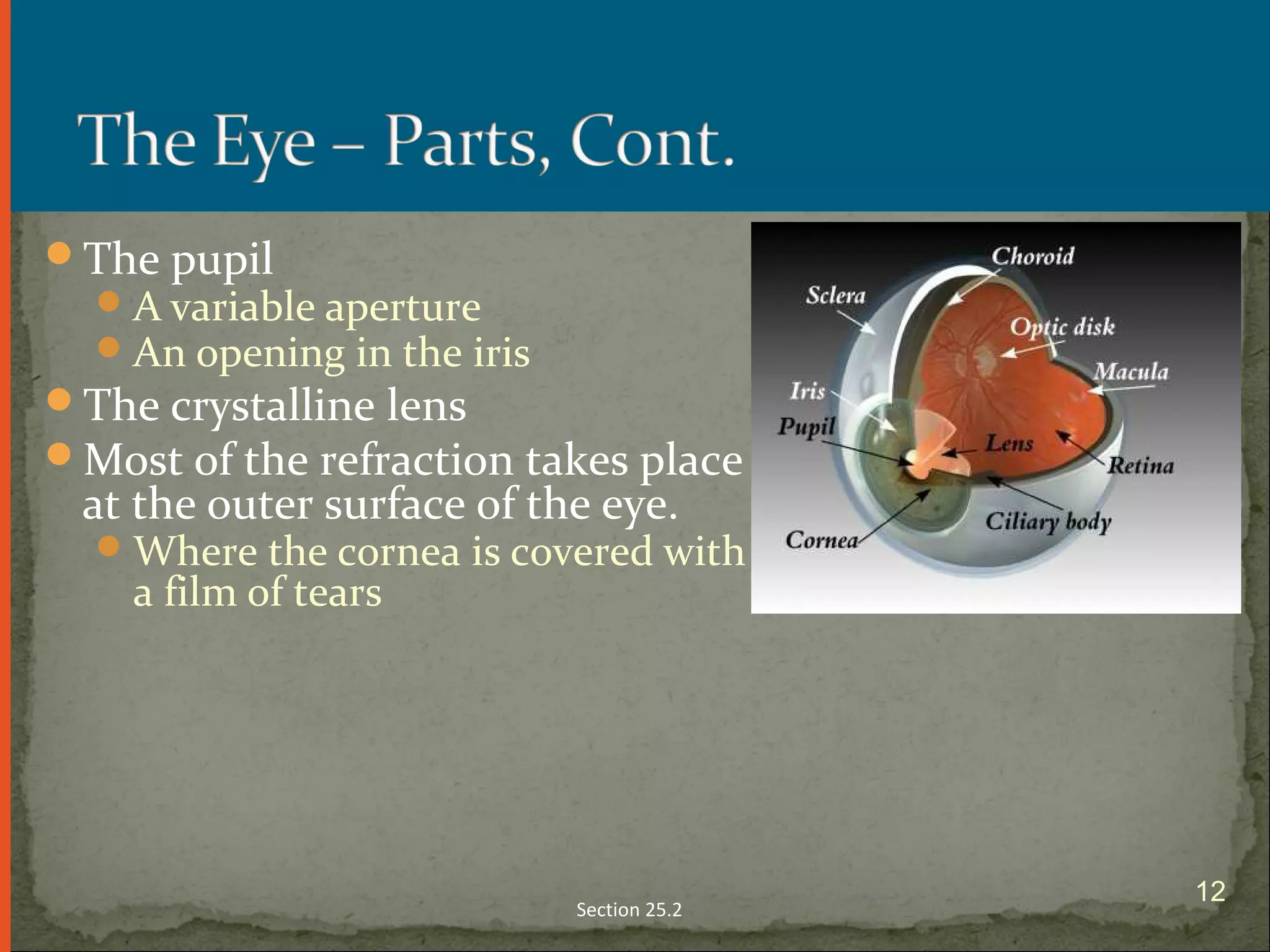
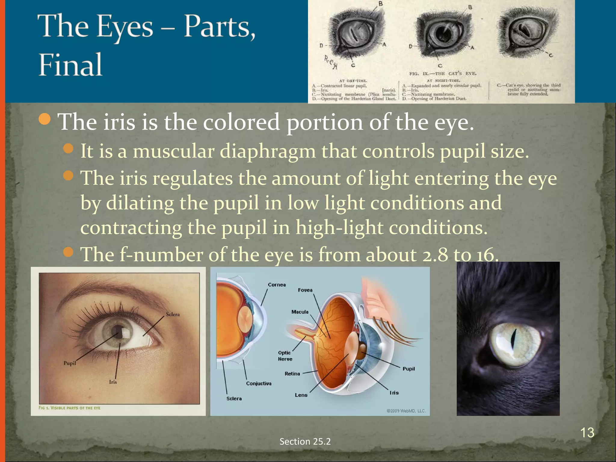
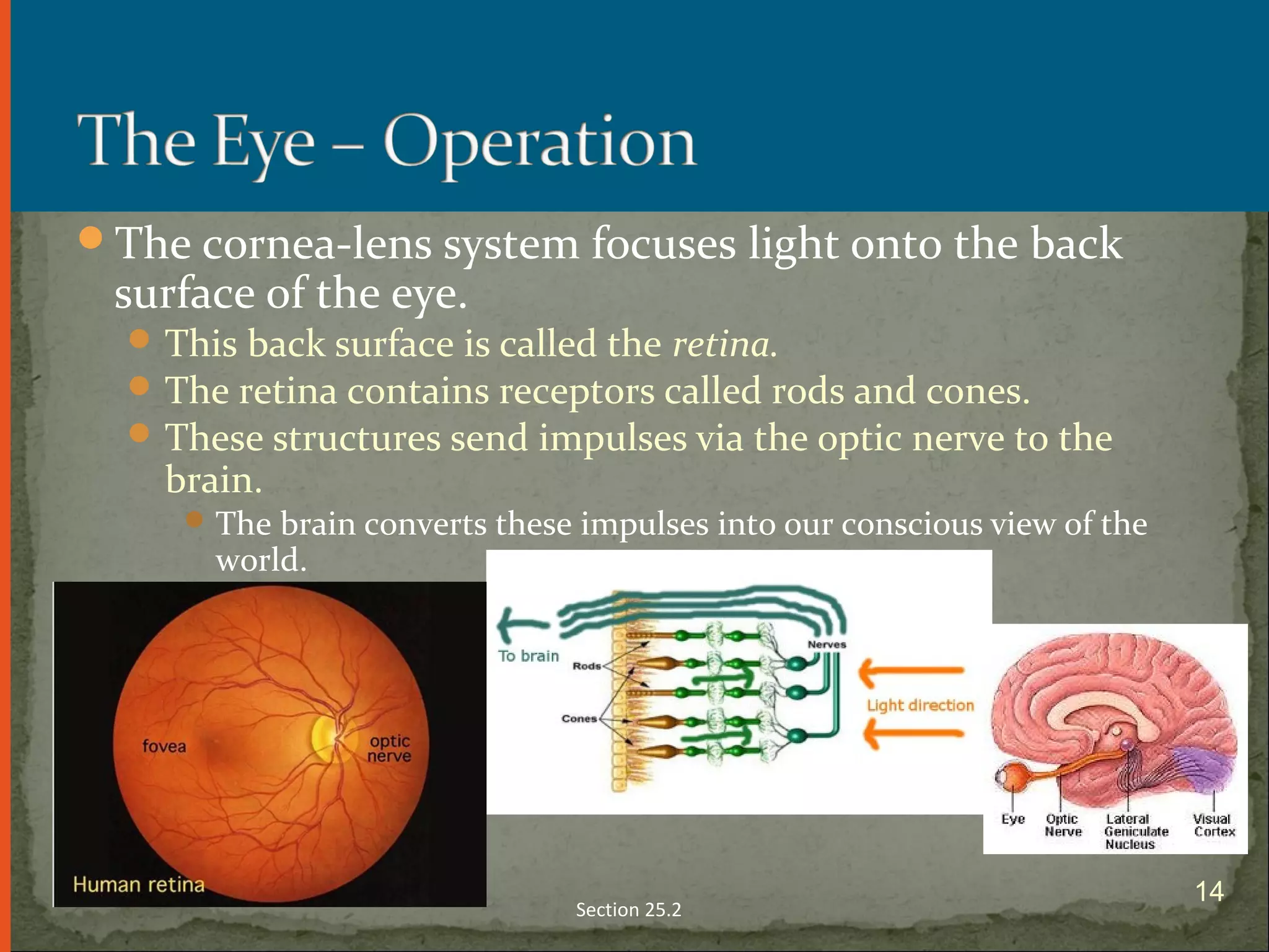
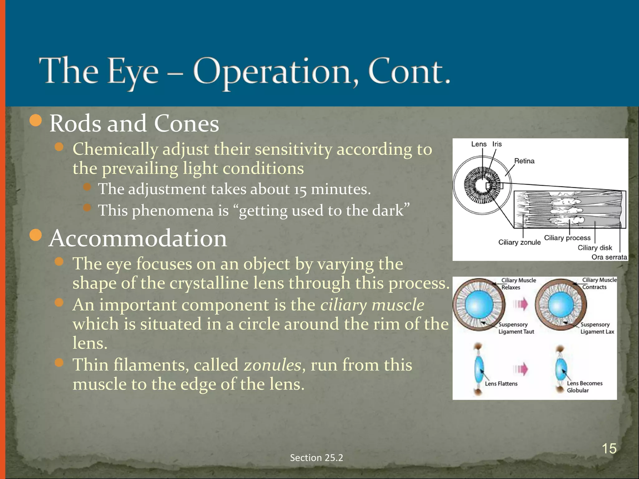
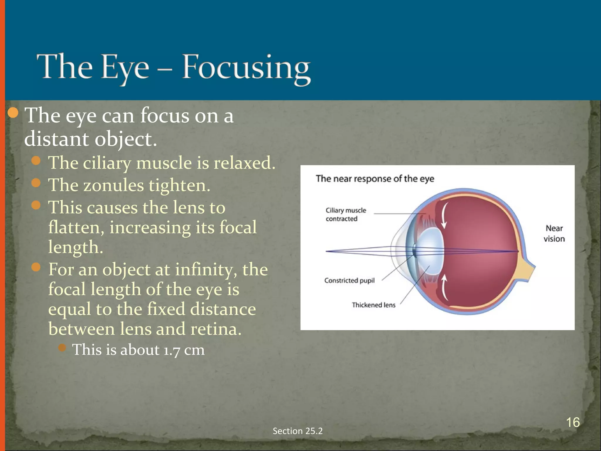
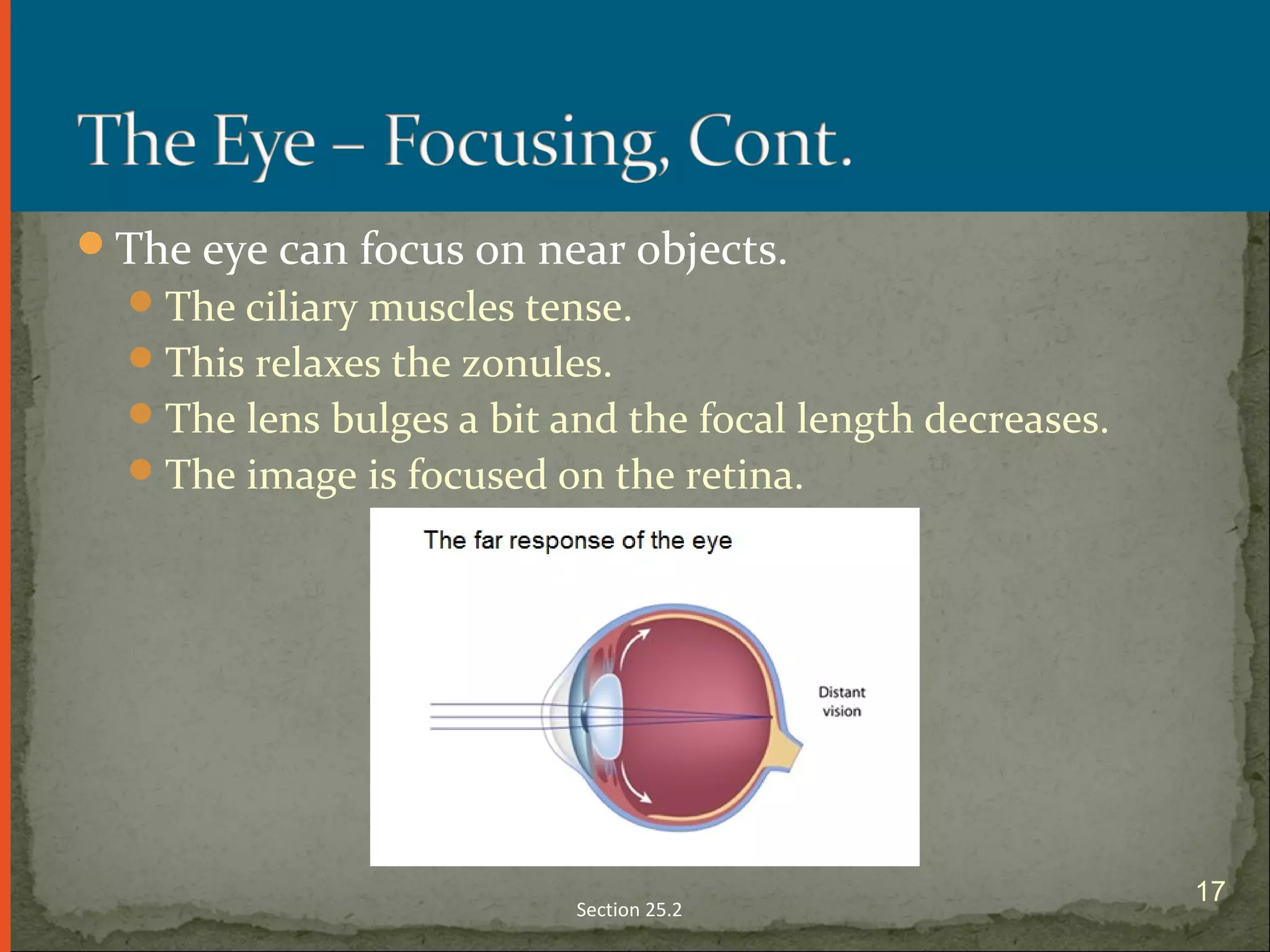
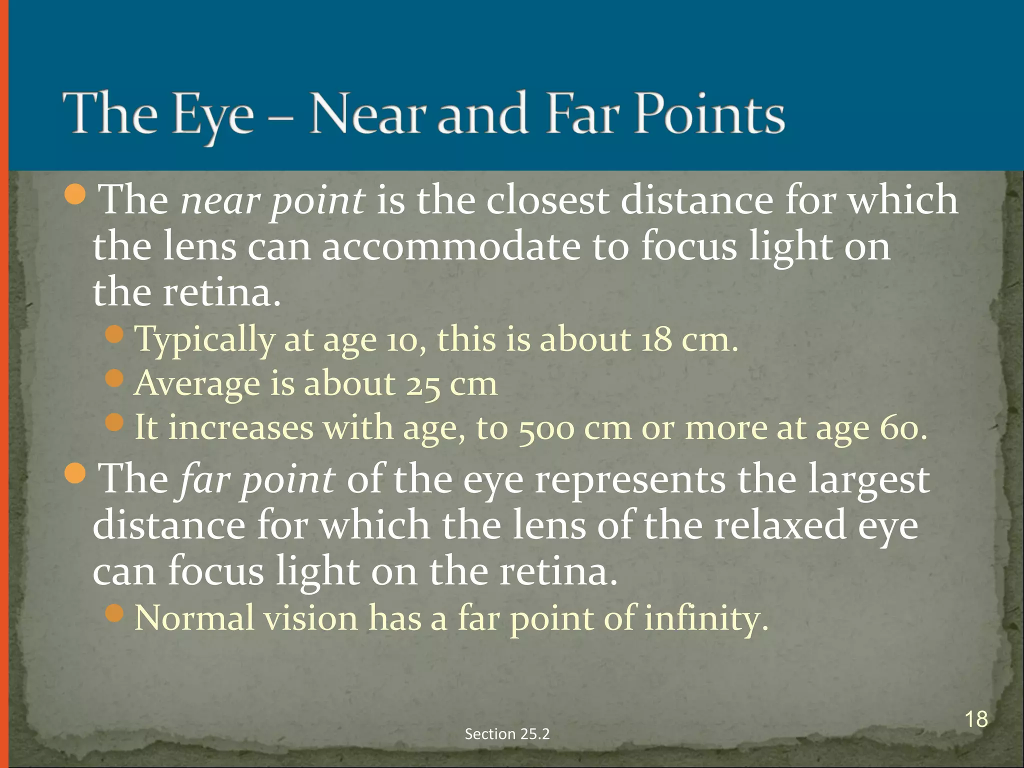
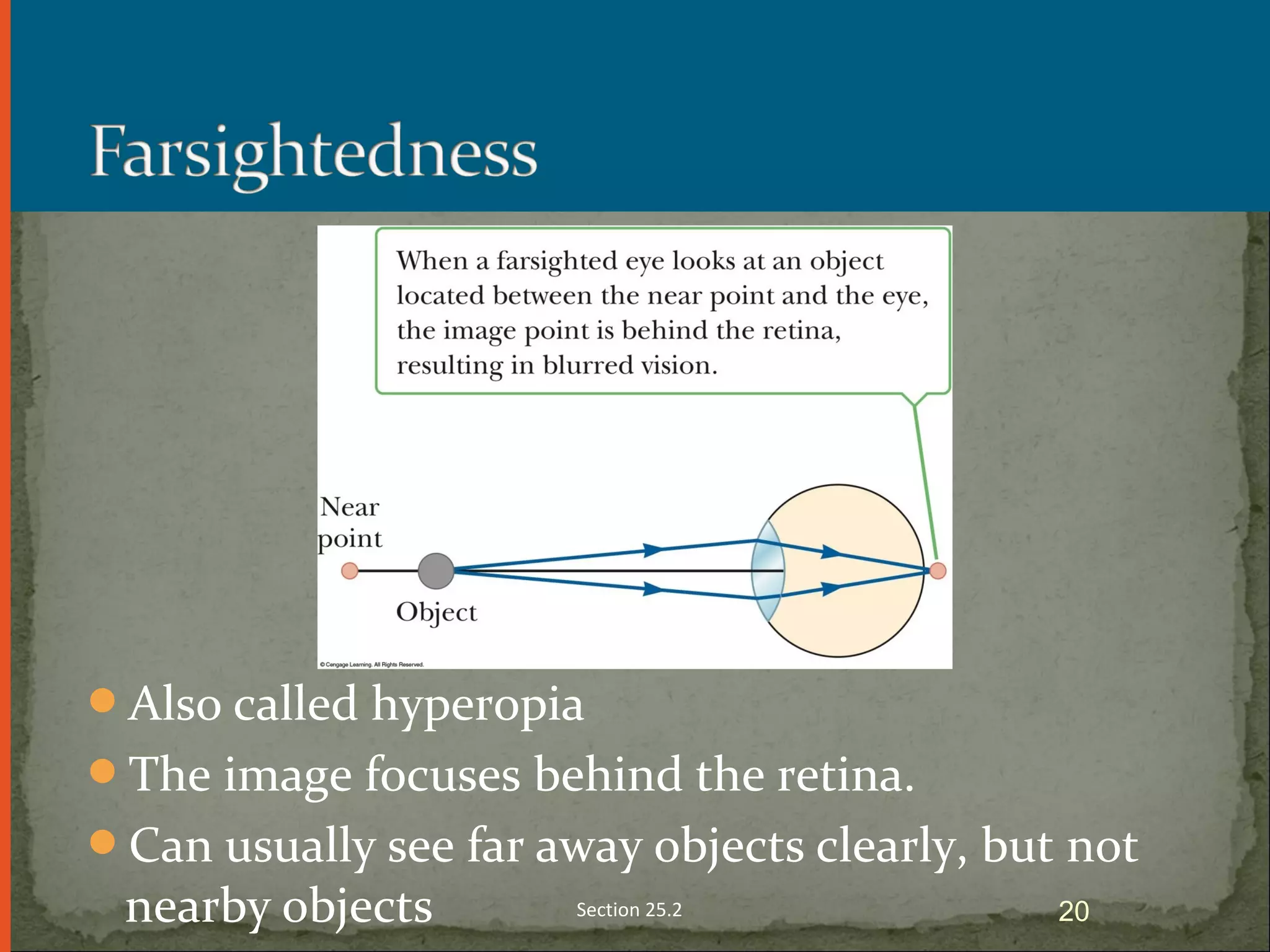
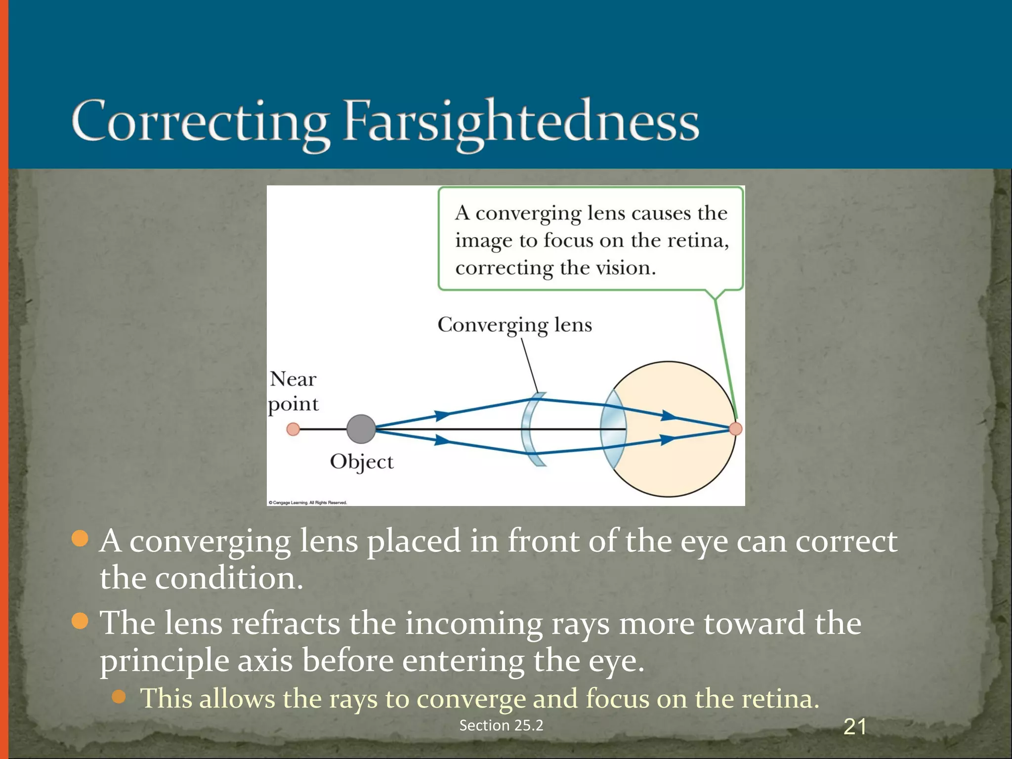
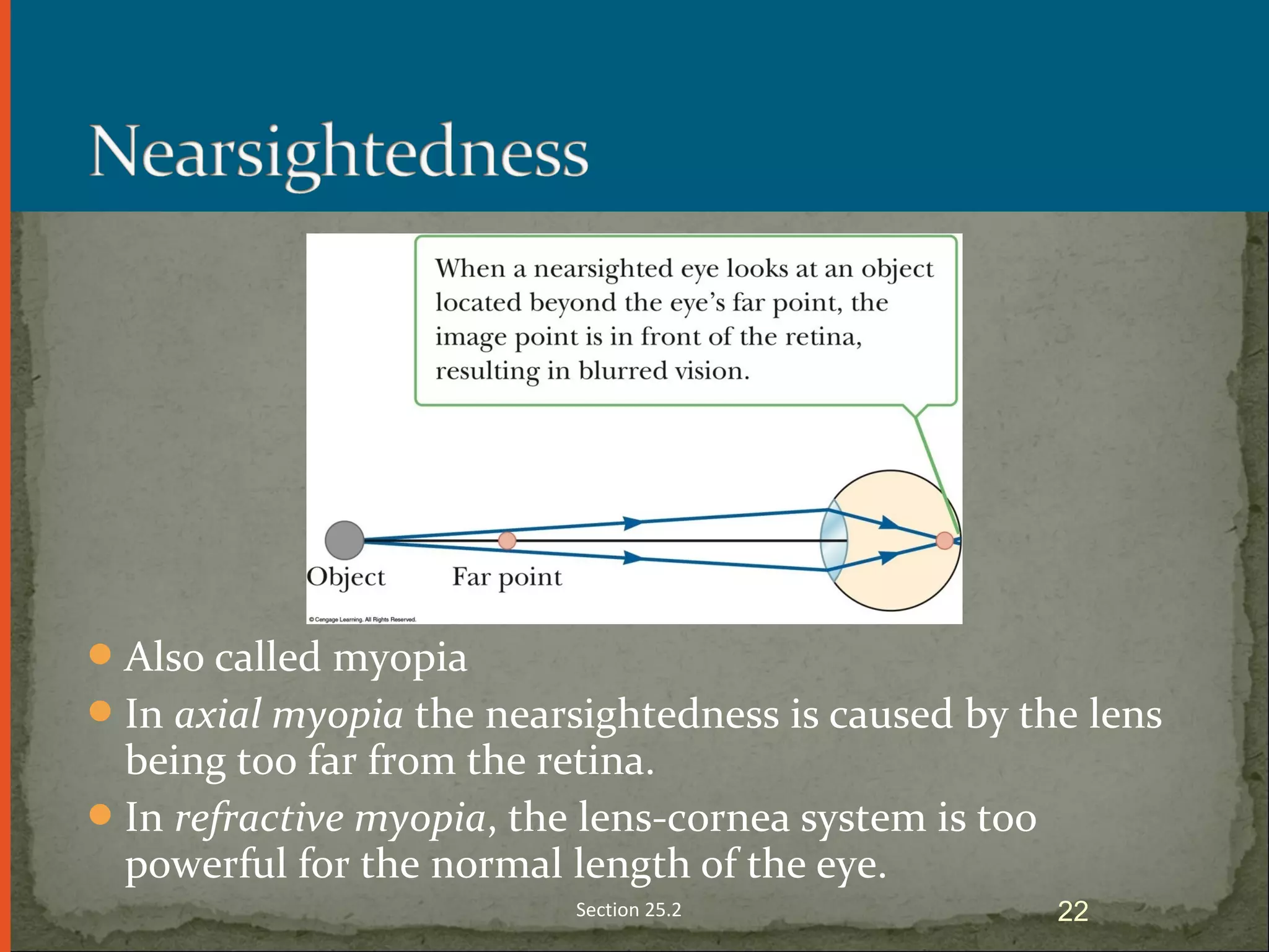
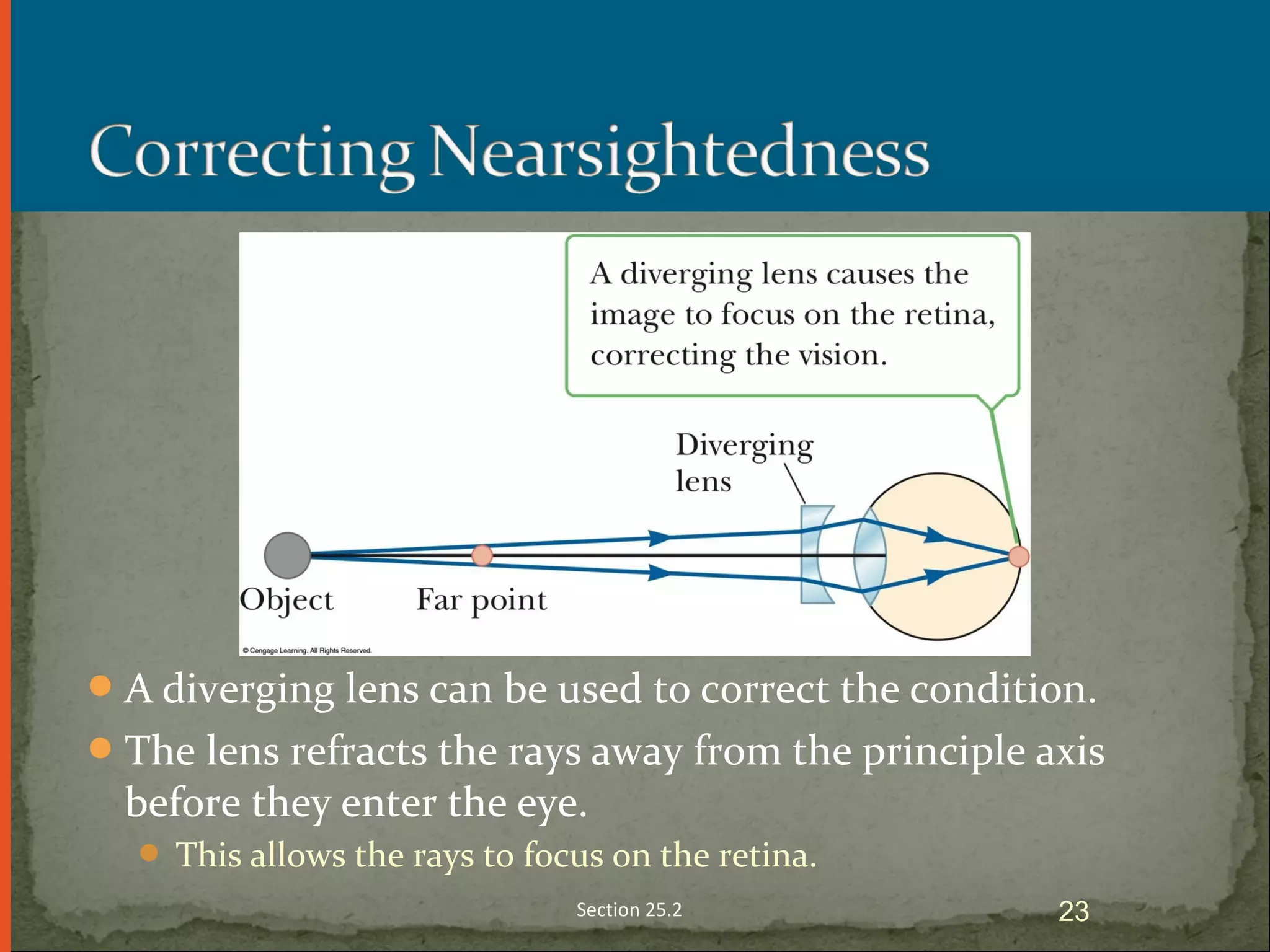
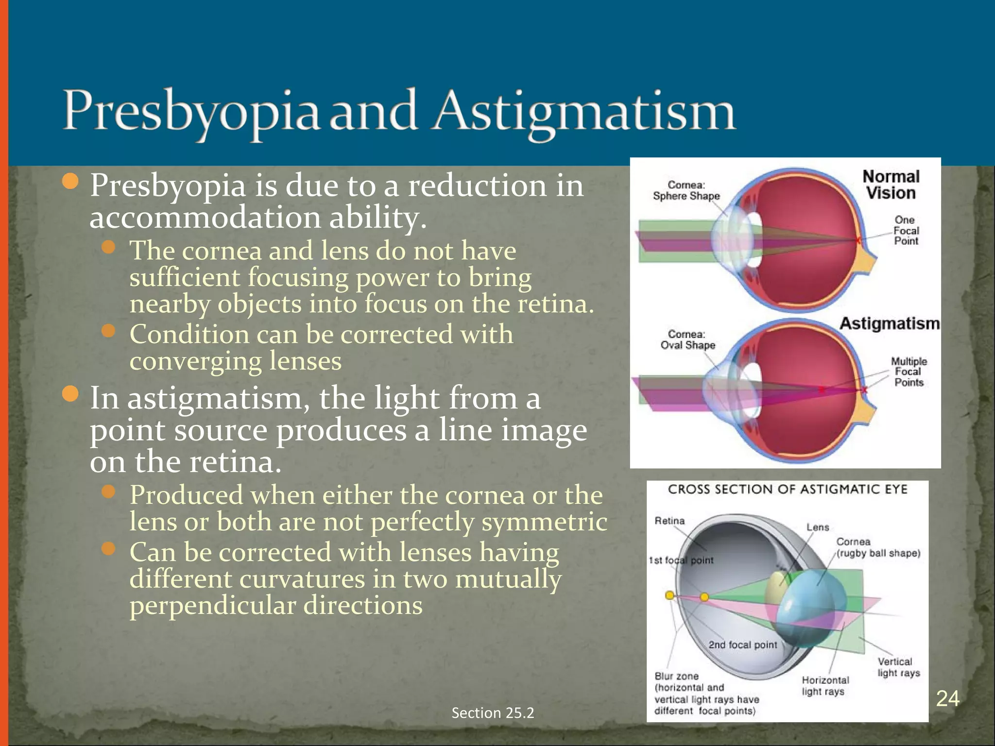
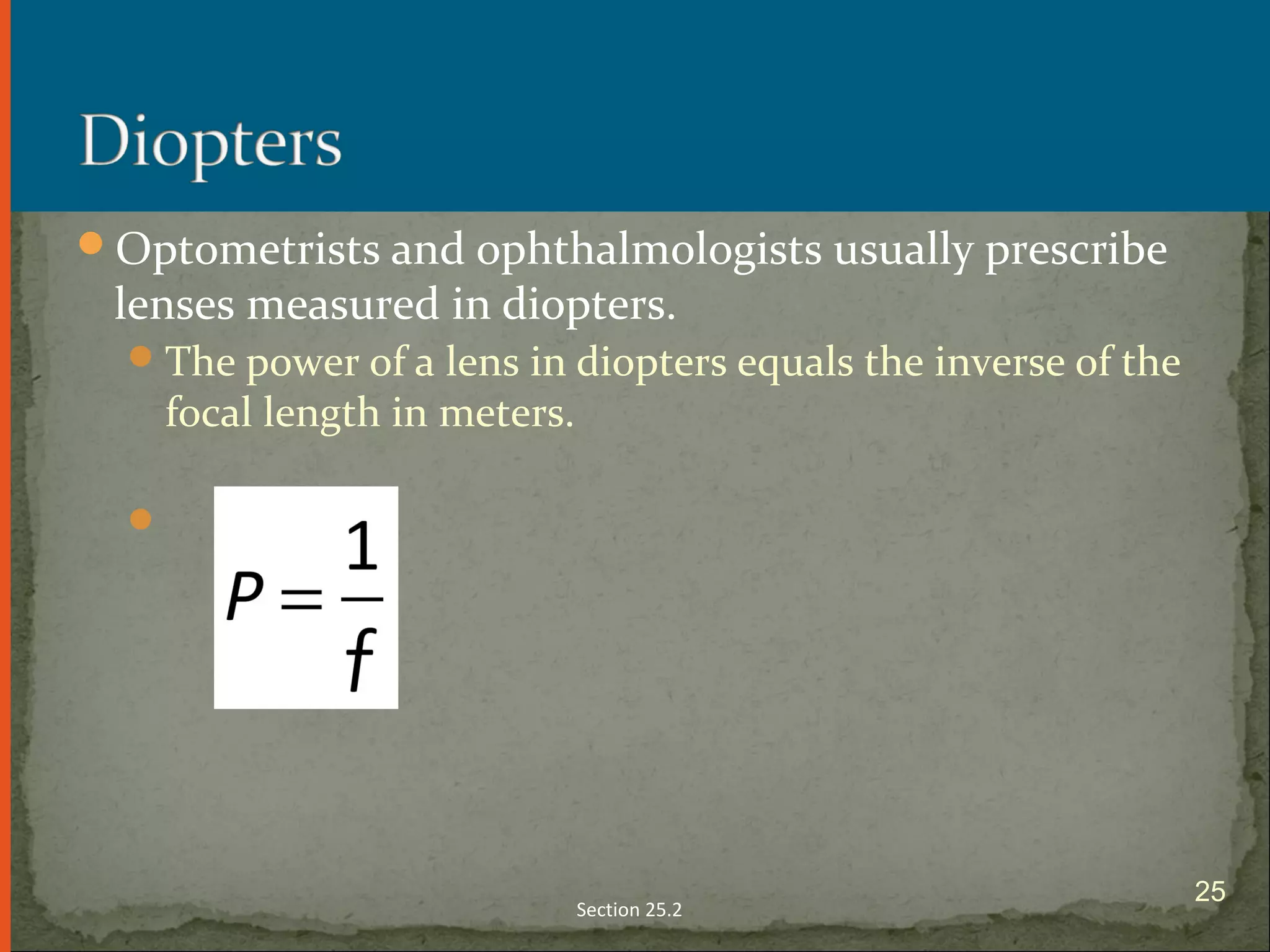
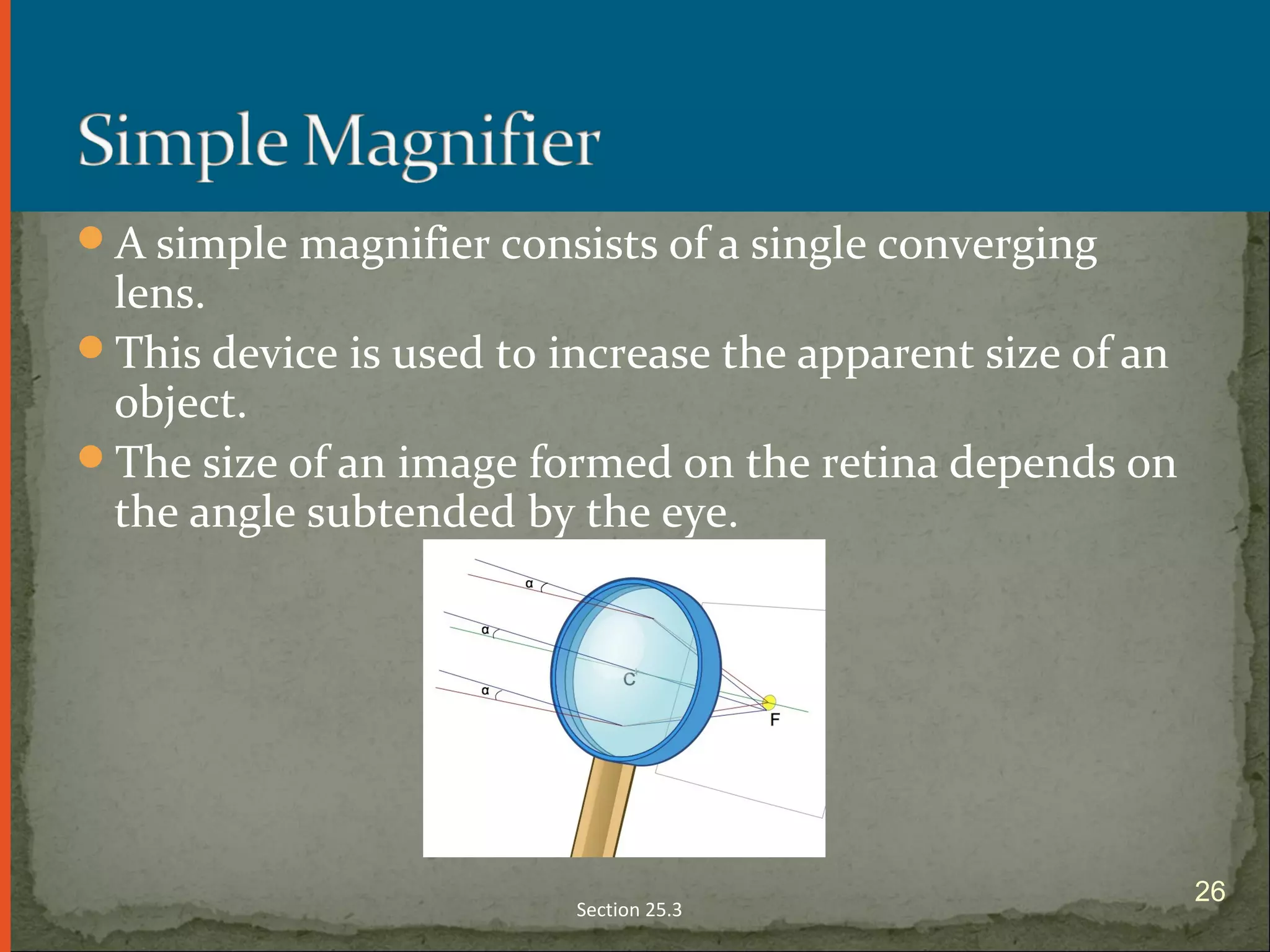
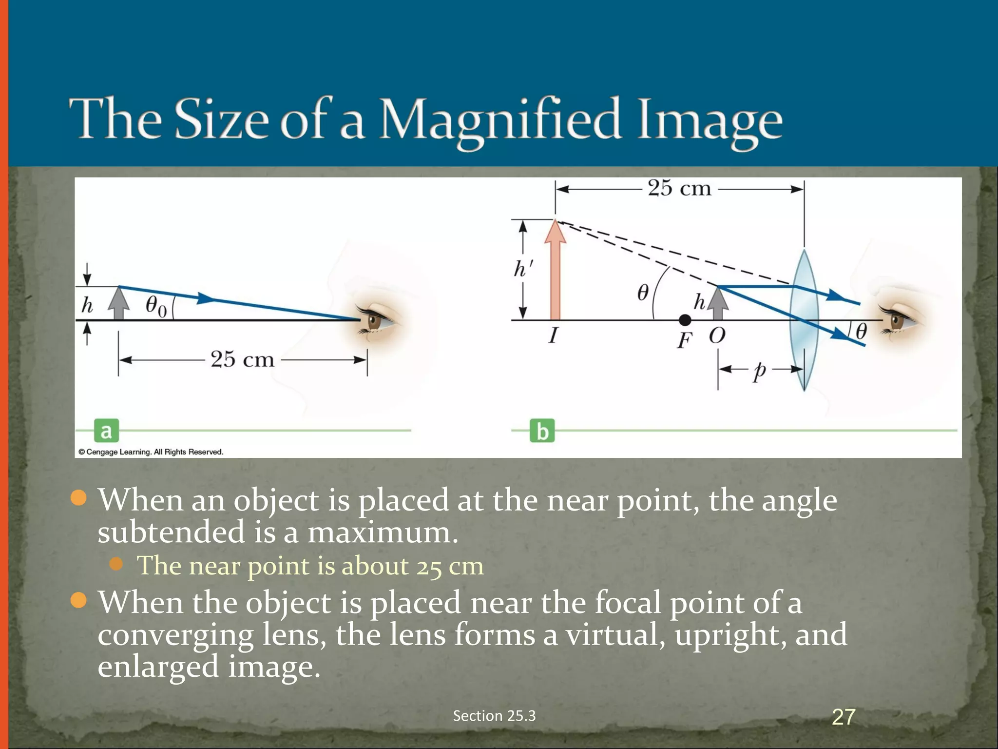
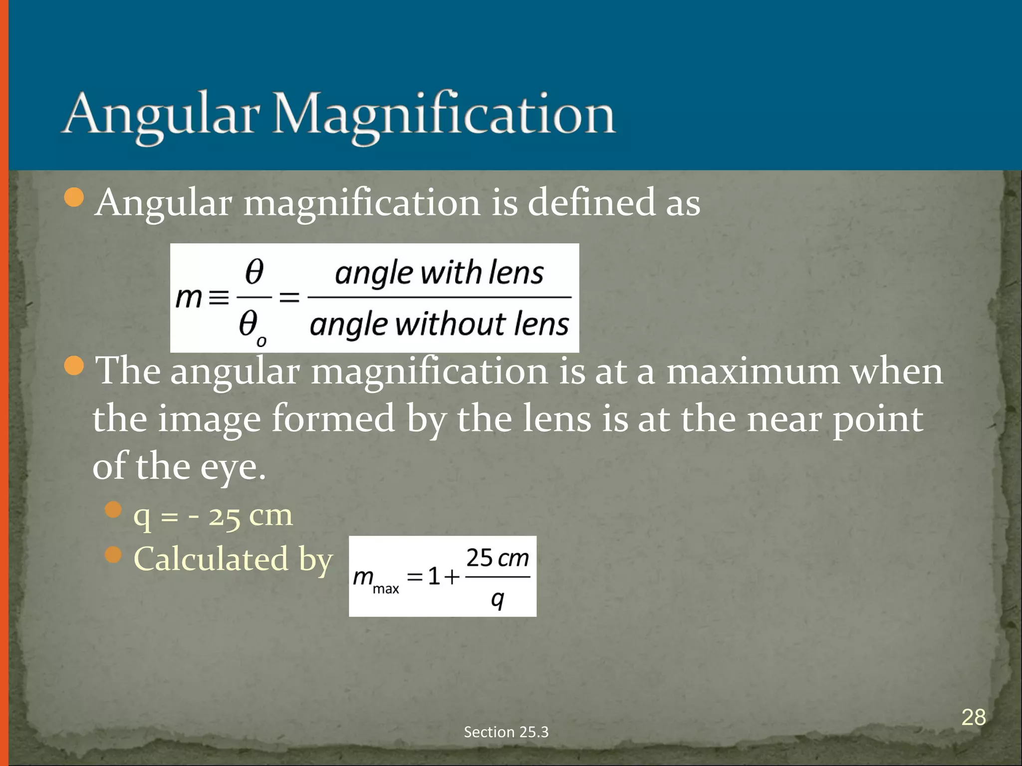
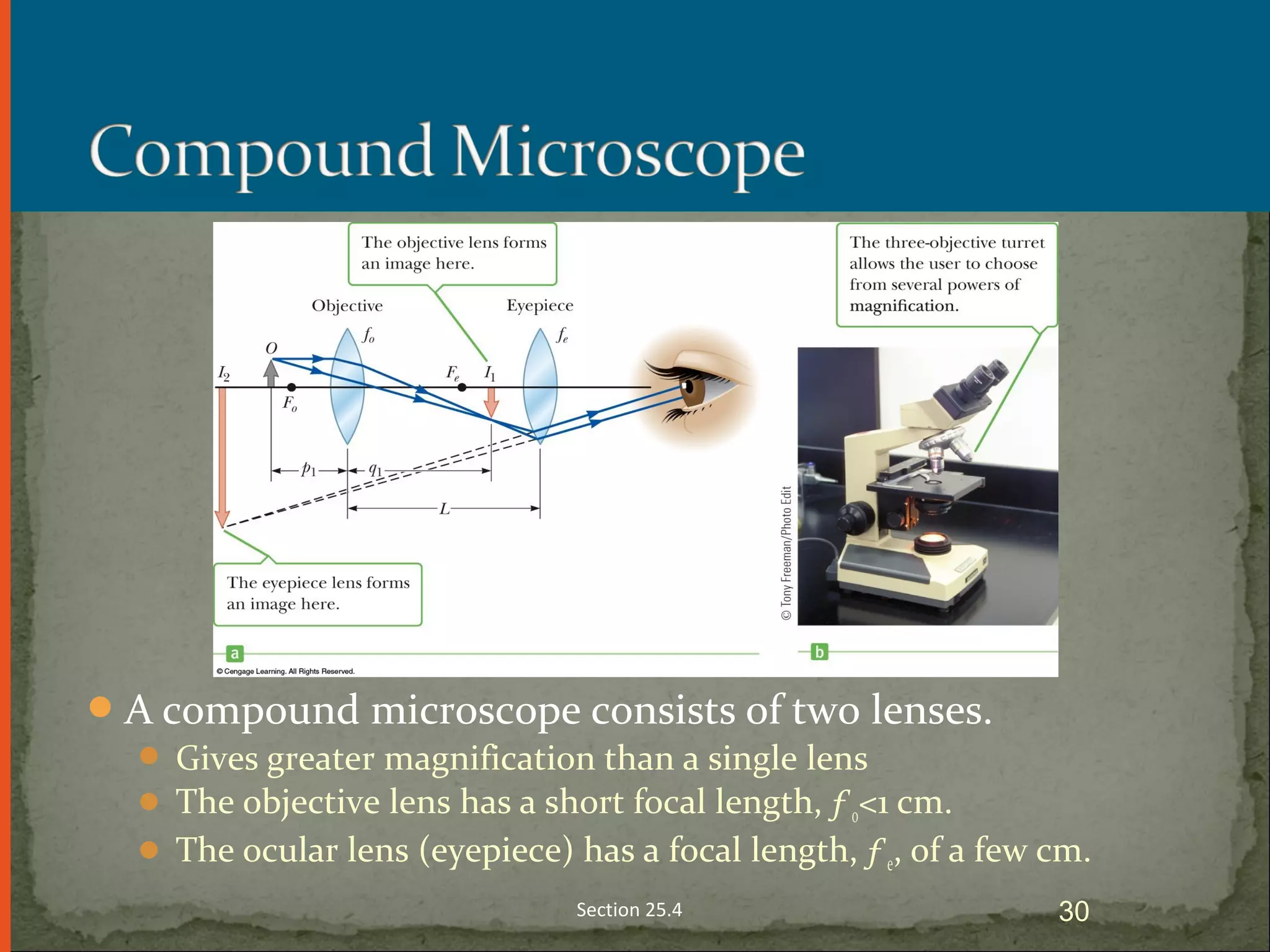
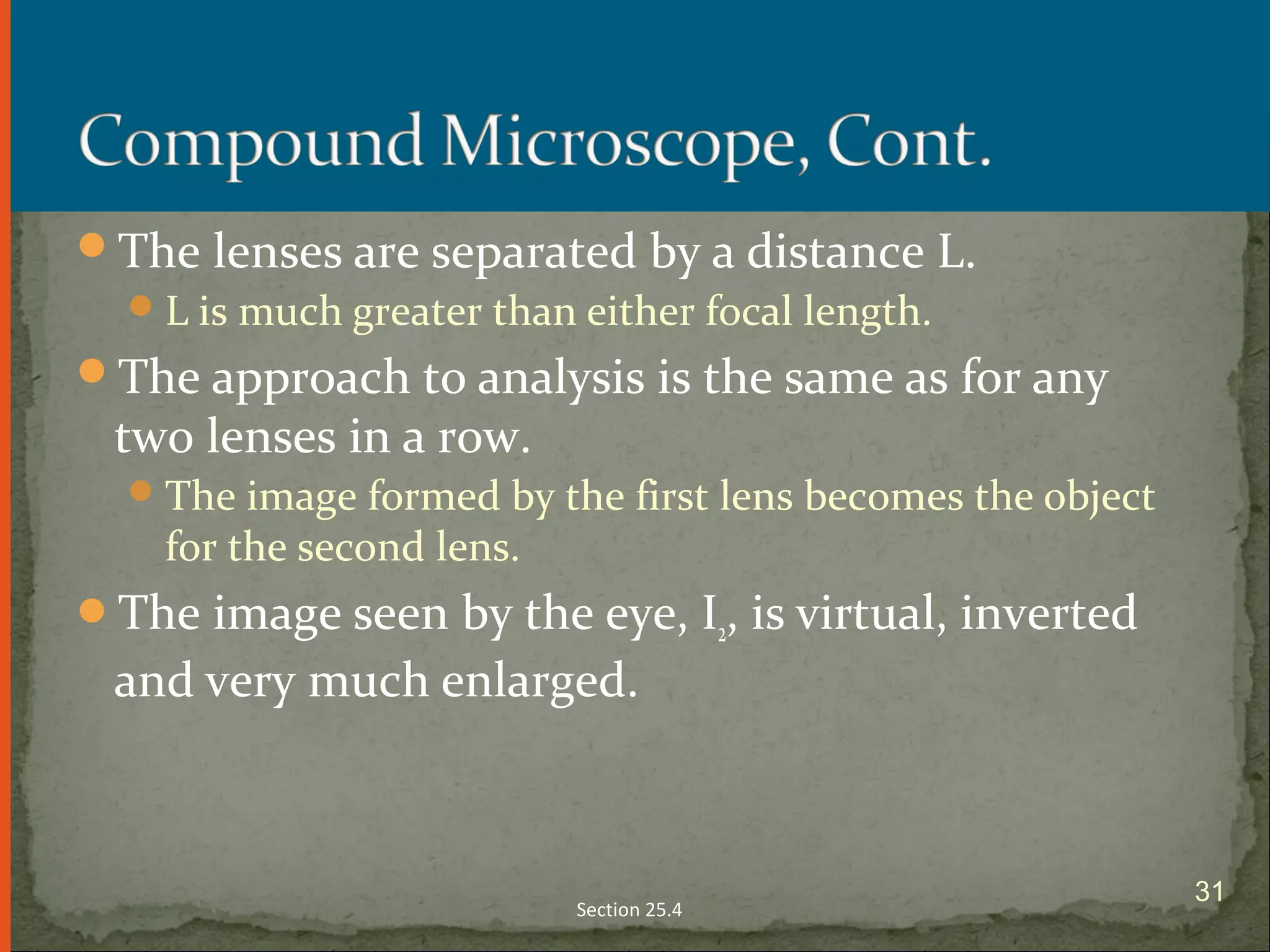
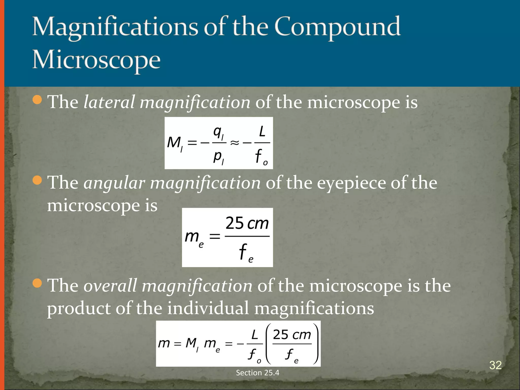
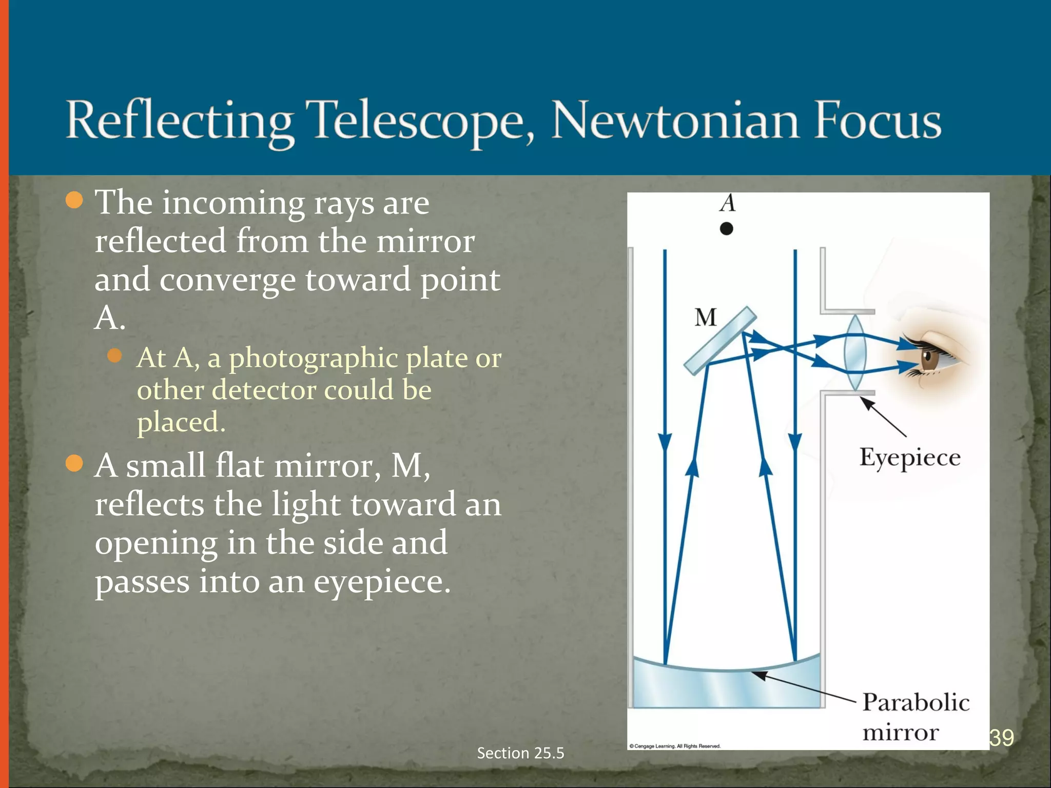
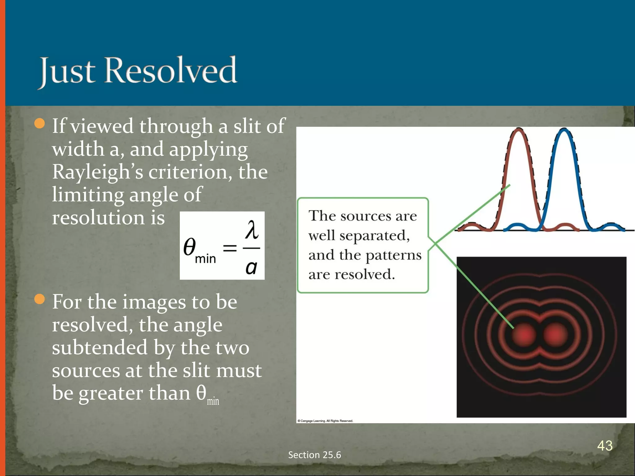
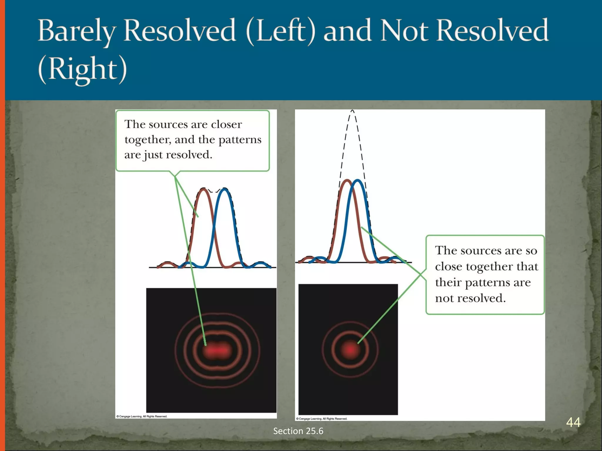
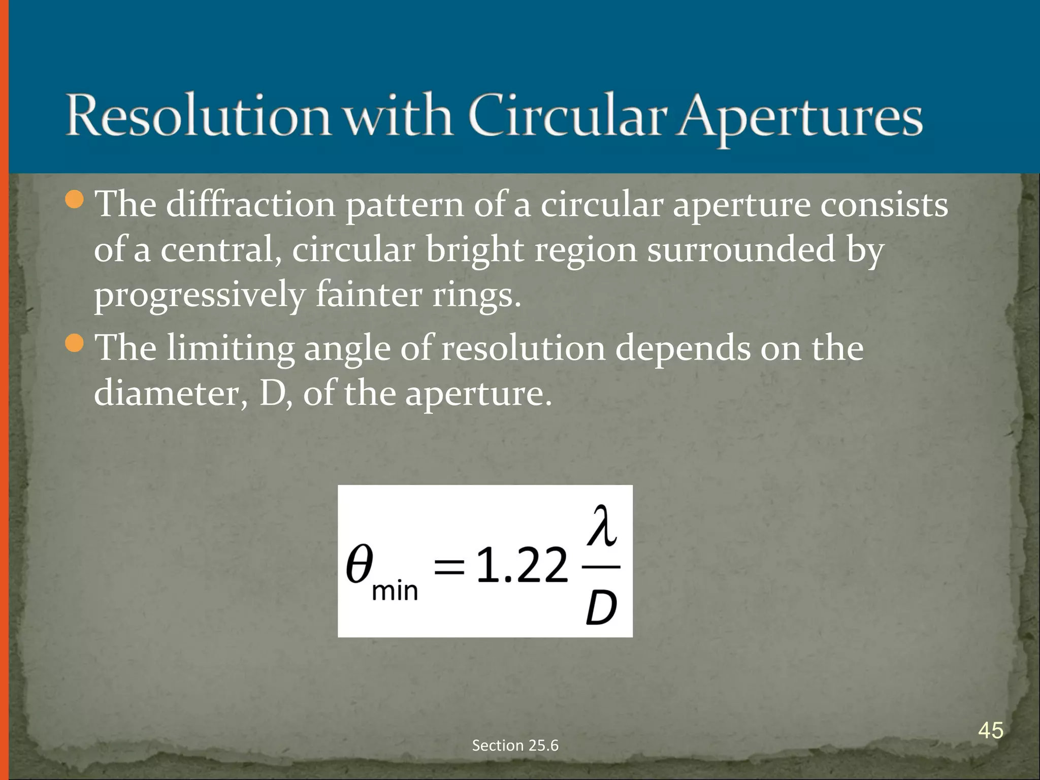
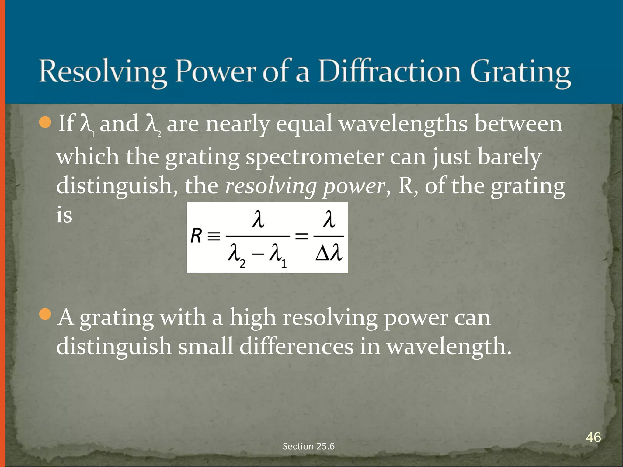
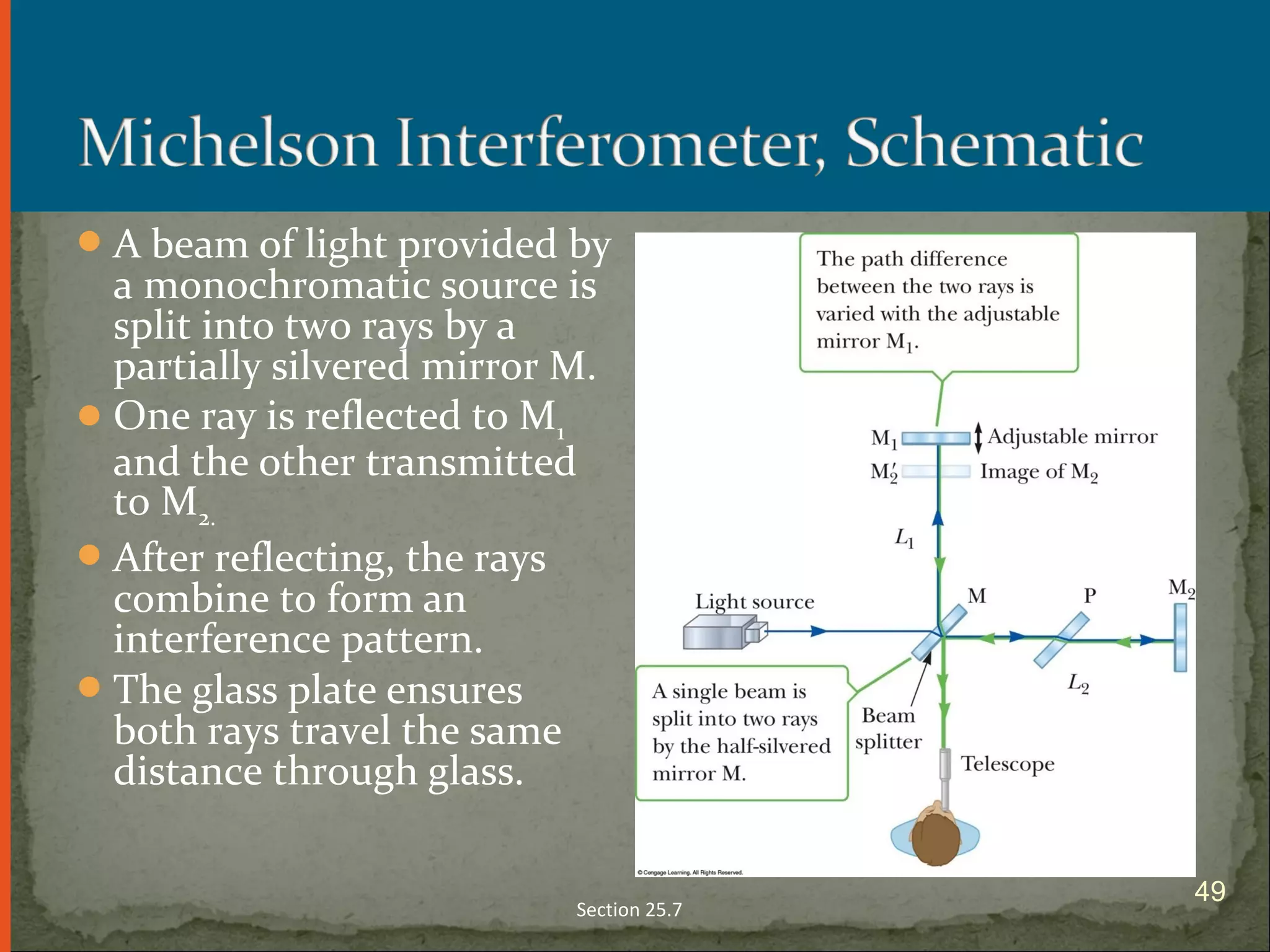
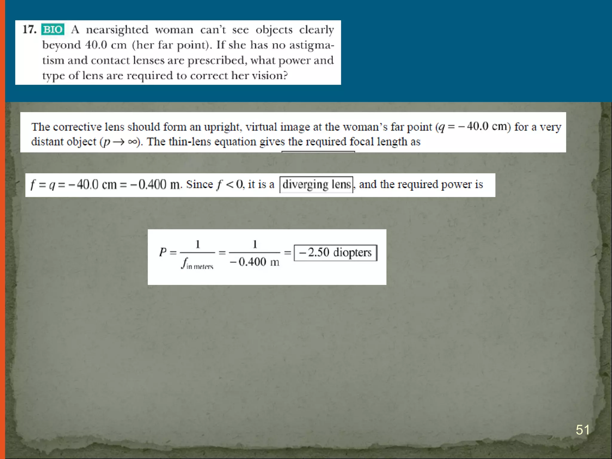
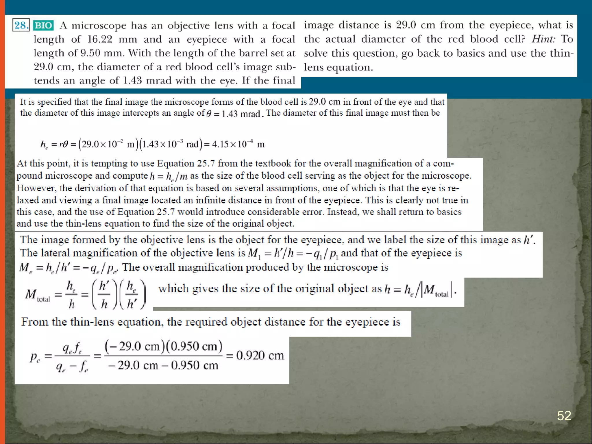
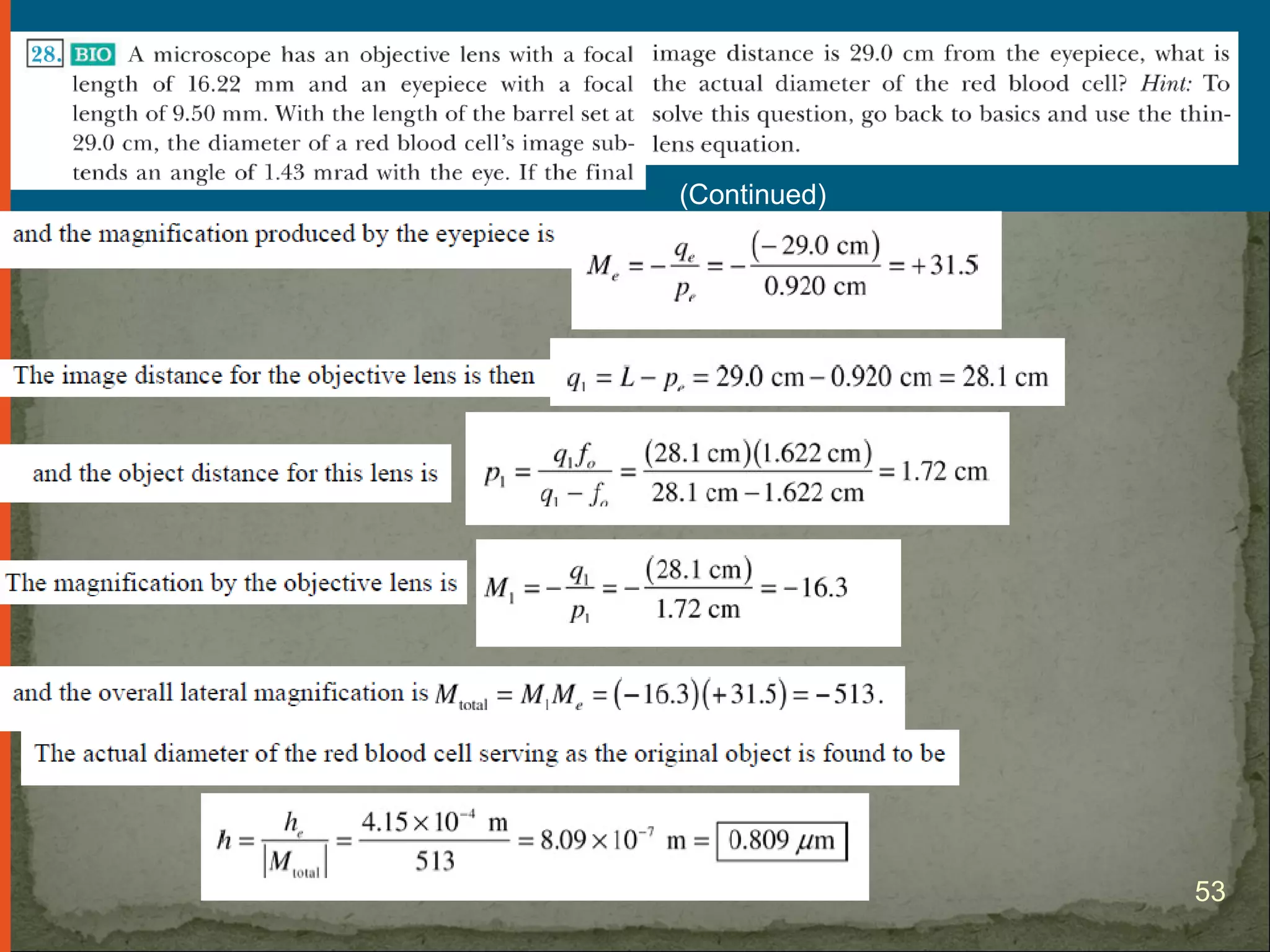
Raymond A. Serway
Chris Vuille
Optical Instruments
1
Analysis generally involves the laws of reflection
and refraction.
Analysis uses the procedures of geometric optics
(Ray model of light).
However, To explain certain phenomena, the wave
nature of light must be used.
Introduction
2
The single-lens photographic camera is an optical
instrument.
Components
Opaque, light-tight box
Converging lens
Produces a real image
Film behind the lens
Receives the image
Section 25.1
3
Image is formed on an
electric device
 CCD – Charge-coupled
device
 CMOS – Complementary
metal-oxide semiconductor
Both convert the image
into digital form.
The image can be stored in
the camera’s memory.
Section 25.1
4
Proper focusing leads to sharp images.
The lens-to-film distance will depend on the object distance
and on the focal length of the lens.
The shutter is a mechanical device that is opened for
selected time intervals.
Most cameras have an aperture of adjustable diameter
to further control the intensity of the light reaching
the film.
With a small-diameter aperture, only light from the central
portion reaches the film, and spherical aberration is
minimized.
Section 25.1
5
Light intensity is a measure of the rate at which
energy is received by the film per unit area of the
image.
The intensity of the light reaching the film is
proportional to the area of the lens.
The brightness of the image formed on the film
depends on the light intensity.
Depends on both the focal length and the diameter of
the lens
Section 25.1
6
The ƒ-number of a camera is the ratio of the focal
length of the lens to its diameter.
ƒ-number = f/D
The ƒ-number is often given as a description of the lens
“speed”.
A lens with a low f-number is a “fast” lens.
Section 25.1
7
8
Increasing the setting from one ƒ-number to the next
higher value decreases the area of the aperture by a
factor of 2.
The lowest ƒ-number setting on a camera corresponds
to the aperture wide open and the maximum possible
lens area in use.
Simple cameras usually have a fixed focal length and a
fixed aperture size, with an ƒ-number of about 11.
The high value of ƒ allows for a large depth-of-field.
Most cameras with variable ƒ-numbers adjust them
automatically.
Section 25.1
Example of
depth of
field 
9
10
The normal eye focuses
light and produces a sharp
image.
Essential parts of the eye
 Cornea – light passes
through this transparent
structure
 Aqueous Humor – clear
liquid behind the cornea
Section 25.2
11
The pupil
A variable aperture
An opening in the iris
The crystalline lens
Most of the refraction takes place
at the outer surface of the eye.
Where the cornea is covered with
a film of tears
Section 25.2
12
The iris is the colored portion of the eye.
It is a muscular diaphragm that controls pupil size.
The iris regulates the amount of light entering the eye
by dilating the pupil in low light conditions and
contracting the pupil in high-light conditions.
The f-number of the eye is from about 2.8 to 16.
Section 25.2
13
The cornea-lens system focuses light onto the back
surface of the eye.
This back surface is called the retina.
The retina contains receptors called rods and cones.
These structures send impulses via the optic nerve to the
brain.
The brain converts these impulses into our conscious view of the
world.
Section 25.2
14
Rods and Cones
 Chemically adjust their sensitivity according to
the prevailing light conditions
 The adjustment takes about 15 minutes.
 This phenomena is “getting used to the dark”
Accommodation
 The eye focuses on an object by varying the
shape of the crystalline lens through this process.
 An important component is the ciliary muscle
which is situated in a circle around the rim of the
lens.
 Thin filaments, called zonules, run from this
muscle to the edge of the lens.
Section 25.2
15
The eye can focus on a
distant object.
The ciliary muscle is relaxed.
The zonules tighten.
This causes the lens to
flatten, increasing its focal
length.
For an object at infinity, the
focal length of the eye is
equal to the fixed distance
between lens and retina.
This is about 1.7 cm
Section 25.2
16
The eye can focus on near objects.
The ciliary muscles tense.
This relaxes the zonules.
The lens bulges a bit and the focal length decreases.
The image is focused on the retina.
Section 25.2
17
The near point is the closest distance for which
the lens can accommodate to focus light on
the retina.
Typically at age 10, this is about 18 cm.
Average is about 25 cm
It increases with age, to 500 cm or more at age 60.
The far point of the eye represents the largest
distance for which the lens of the relaxed eye
can focus light on the retina.
Normal vision has a far point of infinity.
Section 25.2
18
Eyes may suffer a mismatch between the focusing
power of the lens-cornea system and the length of
the eye.
Eyes may be
Farsighted
Light rays reach the retina before they converge to form an
image
Nearsighted
Person can focus on nearby objects but not those far away
Section 25.2
19
Also called hyperopia
The image focuses behind the retina.
Can usually see far away objects clearly, but not
nearby objects Section 25.2 20
A converging lens placed in front of the eye can correct
the condition.
The lens refracts the incoming rays more toward the
principle axis before entering the eye.
 This allows the rays to converge and focus on the retina.
Section 25.2 21
Also called myopia
In axial myopia the nearsightedness is caused by the lens
being too far from the retina.
In refractive myopia, the lens-cornea system is too
powerful for the normal length of the eye.
Section 25.2 22
A diverging lens can be used to correct the condition.
The lens refracts the rays away from the principle axis
before they enter the eye.
 This allows the rays to focus on the retina.
Section 25.2 23
Presbyopia is due to a reduction in
accommodation ability.
 The cornea and lens do not have
sufficient focusing power to bring
nearby objects into focus on the retina.
 Condition can be corrected with
converging lenses
In astigmatism, the light from a
point source produces a line image
on the retina.
 Produced when either the cornea or the
lens or both are not perfectly symmetric
 Can be corrected with lenses having
different curvatures in two mutually
perpendicular directions
Section 25.2
24
Optometrists and ophthalmologists usually prescribe
lenses measured in diopters.
The power of a lens in diopters equals the inverse of the
focal length in meters.

Section 25.2
25
A simple magnifier consists of a single converging
lens.
This device is used to increase the apparent size of an
object.
The size of an image formed on the retina depends on
the angle subtended by the eye.
Section 25.3
26
When an object is placed at the near point, the angle
subtended is a maximum.
 The near point is about 25 cm
When the object is placed near the focal point of a
converging lens, the lens forms a virtual, upright, and
enlarged image.
Section 25.3 27
Angular magnification is defined as
The angular magnification is at a maximum when
the image formed by the lens is at the near point
of the eye.
q = - 25 cm
Calculated by
Section 25.3
28
With a single lens, it is possible to achieve angular
magnification up to about 4 without serious
aberrations.
With multiple lenses, magnifications of up to about
20 can be achieved.
The multiple lenses can correct for aberrations.
Section 25.3
29
A compound microscope consists of two lenses.
 Gives greater magnification than a single lens
 The objective lens has a short focal length, ƒo<1 cm.
 The ocular lens (eyepiece) has a focal length, ƒe, of a few cm.
Section 25.4 30
The lenses are separated by a distance L.
L is much greater than either focal length.
The approach to analysis is the same as for any
two lenses in a row.
The image formed by the first lens becomes the object
for the second lens.
The image seen by the eye, I2, is virtual, inverted
and very much enlarged.
Section 25.4
31
The lateral magnification of the microscope is
The angular magnification of the eyepiece of the
microscope is
The overall magnification of the microscope is the
product of the individual magnifications
Section 25.4
32
The ability of an optical microscope to view an object
depends on the size of the object relative to the
wavelength of the light used to observe it.
For example, you could not observe an atom (d ≈ 0.1
nm) with visible light (λ≈ 500 nm).
Section 25.4
33
Two fundamental types of telescopes
Refracting telescope uses a combination of lenses to
form an image.
Reflecting telescope uses a curved mirror and a lens to
form an image.
Telescopes can be analyzed by considering them
to be two optical elements in a row.
The image of the first element becomes the object of
the second element.
Section 25.5
34
The two lenses are arranged so
that the objective forms a real,
inverted image of a distant
object.
The image is near the focal
point of the eyepiece.
The two lenses are separated
by the distance ƒo + ƒe which
corresponds to the length of
the tube.
The eyepiece forms an
enlarged, inverted image of the
first image.
Section 25.5 35
The angular magnification depends on the focal
lengths of the objective and eyepiece.
Angular magnification is particularly important
for observing nearby objects.
Very distant objects still appear as a small point of light.
Section 25.5
36
Large diameters are needed to study distant objects.
Large lenses are difficult and expensive to
manufacture.
The weight of large lenses leads to sagging which
produces aberrations.
Section 25.5
37
Helps overcome some of the disadvantages of
refracting telescopes
Replaces the objective lens with a mirror
The mirror is often parabolic to overcome spherical
aberrations.
In addition, the light never passes through glass.
Except the eyepiece
Reduced chromatic aberrations
Section 25.5
38
The incoming rays are
reflected from the mirror
and converge toward point
A.
 At A, a photographic plate or
other detector could be
placed.
A small flat mirror, M,
reflects the light toward an
opening in the side and
passes into an eyepiece.
Section 25.5
39
Reflecting Telescopes
Largest in the world are 10 m diameter Keck telescopes
on Mauna Kea in Hawaii
Largest single mirror in US is 5 m diameter instrument
on Mount Palomar in California
Refracting Telescopes
Largest in the world is Yerkes Observatory in Wisconsin
Has a 1 m diameter
Section 25.5
40
The ability of an optical system to distinguish
between closely spaced objects is limited due to
the wave nature of light.
If two sources of light are close together, they can
be treated as non-coherent sources.
Because of diffraction, the images consist of bright
central regions flanked by weaker bright and dark
rings.
Section 25.6
41
If the two sources are separated so that their
central maxima do not overlap, their images are
said to be resolved.
The limiting condition for resolution is Rayleigh’s
Criterion.
When the central maximum of one image falls on the
first minimum of another image, they images are said to
be just resolved.
The images are just resolved when their angular
separation satisfies Rayleigh’s criterion.
Section 25.6
42
If viewed through a slit of
width a, and applying
Rayleigh’s criterion, the
limiting angle of
resolution is
For the images to be
resolved, the angle
subtended by the two
sources at the slit must
be greater than θmin
Section 25.6
43
Section 25.6
44
The diffraction pattern of a circular aperture consists
of a central, circular bright region surrounded by
progressively fainter rings.
The limiting angle of resolution depends on the
diameter, D, of the aperture.
Section 25.6
45
If λ1 and λ2 are nearly equal wavelengths between
which the grating spectrometer can just barely
distinguish, the resolving power, R, of the grating
is
A grating with a high resolving power can
distinguish small differences in wavelength.
Section 25.6
46
The resolving power increases with order number.
R = Nm
N is the number of lines illuminated.
m is the order number.
All wavelengths are indistinguishable for the zeroth-
order maximum.
m = 0 so R = 0
Section 25.6
47
The Michelson Interferometer is an optical
instrument that has great scientific importance.
It splits a beam of light into two parts and then
recombines them to form an interference pattern.
It is used to make accurate length measurements.
Section 25.7
48
A beam of light provided by
a monochromatic source is
split into two rays by a
partially silvered mirror M.
One ray is reflected to M1
and the other transmitted
to M2.
After reflecting, the rays
combine to form an
interference pattern.
The glass plate ensures
both rays travel the same
distance through glass.
Section 25.7
49
The interference pattern for the two rays is determined by
the difference in their path lengths.
When M1 is moved a distance of λ/4, successive light and
dark fringes are formed.
This change in a fringe from light to dark is called fringe
shift.
The wavelength can be measured by counting the number
of fringe shifts for a measured displacement of M.
If the wavelength is accurately known, the mirror
displacement can be determined to within a fraction of the
wavelength.
Section 25.7
50
51
52
53
(Continued)
54

chapter25 Optical Instruments

  • 1.
    Raymond A. Serway ChrisVuille Optical Instruments 1
  • 2.
    Analysis generally involvesthe laws of reflection and refraction. Analysis uses the procedures of geometric optics (Ray model of light). However, To explain certain phenomena, the wave nature of light must be used. Introduction 2
  • 3.
    The single-lens photographiccamera is an optical instrument. Components Opaque, light-tight box Converging lens Produces a real image Film behind the lens Receives the image Section 25.1 3
  • 4.
    Image is formedon an electric device  CCD – Charge-coupled device  CMOS – Complementary metal-oxide semiconductor Both convert the image into digital form. The image can be stored in the camera’s memory. Section 25.1 4
  • 5.
    Proper focusing leadsto sharp images. The lens-to-film distance will depend on the object distance and on the focal length of the lens. The shutter is a mechanical device that is opened for selected time intervals. Most cameras have an aperture of adjustable diameter to further control the intensity of the light reaching the film. With a small-diameter aperture, only light from the central portion reaches the film, and spherical aberration is minimized. Section 25.1 5
  • 6.
    Light intensity isa measure of the rate at which energy is received by the film per unit area of the image. The intensity of the light reaching the film is proportional to the area of the lens. The brightness of the image formed on the film depends on the light intensity. Depends on both the focal length and the diameter of the lens Section 25.1 6
  • 7.
    The ƒ-number ofa camera is the ratio of the focal length of the lens to its diameter. ƒ-number = f/D The ƒ-number is often given as a description of the lens “speed”. A lens with a low f-number is a “fast” lens. Section 25.1 7
  • 8.
  • 9.
    Increasing the settingfrom one ƒ-number to the next higher value decreases the area of the aperture by a factor of 2. The lowest ƒ-number setting on a camera corresponds to the aperture wide open and the maximum possible lens area in use. Simple cameras usually have a fixed focal length and a fixed aperture size, with an ƒ-number of about 11. The high value of ƒ allows for a large depth-of-field. Most cameras with variable ƒ-numbers adjust them automatically. Section 25.1 Example of depth of field  9
  • 10.
  • 11.
    The normal eyefocuses light and produces a sharp image. Essential parts of the eye  Cornea – light passes through this transparent structure  Aqueous Humor – clear liquid behind the cornea Section 25.2 11
  • 12.
    The pupil A variableaperture An opening in the iris The crystalline lens Most of the refraction takes place at the outer surface of the eye. Where the cornea is covered with a film of tears Section 25.2 12
  • 13.
    The iris isthe colored portion of the eye. It is a muscular diaphragm that controls pupil size. The iris regulates the amount of light entering the eye by dilating the pupil in low light conditions and contracting the pupil in high-light conditions. The f-number of the eye is from about 2.8 to 16. Section 25.2 13
  • 14.
    The cornea-lens systemfocuses light onto the back surface of the eye. This back surface is called the retina. The retina contains receptors called rods and cones. These structures send impulses via the optic nerve to the brain. The brain converts these impulses into our conscious view of the world. Section 25.2 14
  • 15.
    Rods and Cones Chemically adjust their sensitivity according to the prevailing light conditions  The adjustment takes about 15 minutes.  This phenomena is “getting used to the dark” Accommodation  The eye focuses on an object by varying the shape of the crystalline lens through this process.  An important component is the ciliary muscle which is situated in a circle around the rim of the lens.  Thin filaments, called zonules, run from this muscle to the edge of the lens. Section 25.2 15
  • 16.
    The eye canfocus on a distant object. The ciliary muscle is relaxed. The zonules tighten. This causes the lens to flatten, increasing its focal length. For an object at infinity, the focal length of the eye is equal to the fixed distance between lens and retina. This is about 1.7 cm Section 25.2 16
  • 17.
    The eye canfocus on near objects. The ciliary muscles tense. This relaxes the zonules. The lens bulges a bit and the focal length decreases. The image is focused on the retina. Section 25.2 17
  • 18.
    The near pointis the closest distance for which the lens can accommodate to focus light on the retina. Typically at age 10, this is about 18 cm. Average is about 25 cm It increases with age, to 500 cm or more at age 60. The far point of the eye represents the largest distance for which the lens of the relaxed eye can focus light on the retina. Normal vision has a far point of infinity. Section 25.2 18
  • 19.
    Eyes may suffera mismatch between the focusing power of the lens-cornea system and the length of the eye. Eyes may be Farsighted Light rays reach the retina before they converge to form an image Nearsighted Person can focus on nearby objects but not those far away Section 25.2 19
  • 20.
    Also called hyperopia Theimage focuses behind the retina. Can usually see far away objects clearly, but not nearby objects Section 25.2 20
  • 21.
    A converging lensplaced in front of the eye can correct the condition. The lens refracts the incoming rays more toward the principle axis before entering the eye.  This allows the rays to converge and focus on the retina. Section 25.2 21
  • 22.
    Also called myopia Inaxial myopia the nearsightedness is caused by the lens being too far from the retina. In refractive myopia, the lens-cornea system is too powerful for the normal length of the eye. Section 25.2 22
  • 23.
    A diverging lenscan be used to correct the condition. The lens refracts the rays away from the principle axis before they enter the eye.  This allows the rays to focus on the retina. Section 25.2 23
  • 24.
    Presbyopia is dueto a reduction in accommodation ability.  The cornea and lens do not have sufficient focusing power to bring nearby objects into focus on the retina.  Condition can be corrected with converging lenses In astigmatism, the light from a point source produces a line image on the retina.  Produced when either the cornea or the lens or both are not perfectly symmetric  Can be corrected with lenses having different curvatures in two mutually perpendicular directions Section 25.2 24
  • 25.
    Optometrists and ophthalmologistsusually prescribe lenses measured in diopters. The power of a lens in diopters equals the inverse of the focal length in meters.  Section 25.2 25
  • 26.
    A simple magnifierconsists of a single converging lens. This device is used to increase the apparent size of an object. The size of an image formed on the retina depends on the angle subtended by the eye. Section 25.3 26
  • 27.
    When an objectis placed at the near point, the angle subtended is a maximum.  The near point is about 25 cm When the object is placed near the focal point of a converging lens, the lens forms a virtual, upright, and enlarged image. Section 25.3 27
  • 28.
    Angular magnification isdefined as The angular magnification is at a maximum when the image formed by the lens is at the near point of the eye. q = - 25 cm Calculated by Section 25.3 28
  • 29.
    With a singlelens, it is possible to achieve angular magnification up to about 4 without serious aberrations. With multiple lenses, magnifications of up to about 20 can be achieved. The multiple lenses can correct for aberrations. Section 25.3 29
  • 30.
    A compound microscopeconsists of two lenses.  Gives greater magnification than a single lens  The objective lens has a short focal length, ƒo<1 cm.  The ocular lens (eyepiece) has a focal length, ƒe, of a few cm. Section 25.4 30
  • 31.
    The lenses areseparated by a distance L. L is much greater than either focal length. The approach to analysis is the same as for any two lenses in a row. The image formed by the first lens becomes the object for the second lens. The image seen by the eye, I2, is virtual, inverted and very much enlarged. Section 25.4 31
  • 32.
    The lateral magnificationof the microscope is The angular magnification of the eyepiece of the microscope is The overall magnification of the microscope is the product of the individual magnifications Section 25.4 32
  • 33.
    The ability ofan optical microscope to view an object depends on the size of the object relative to the wavelength of the light used to observe it. For example, you could not observe an atom (d ≈ 0.1 nm) with visible light (λ≈ 500 nm). Section 25.4 33
  • 34.
    Two fundamental typesof telescopes Refracting telescope uses a combination of lenses to form an image. Reflecting telescope uses a curved mirror and a lens to form an image. Telescopes can be analyzed by considering them to be two optical elements in a row. The image of the first element becomes the object of the second element. Section 25.5 34
  • 35.
    The two lensesare arranged so that the objective forms a real, inverted image of a distant object. The image is near the focal point of the eyepiece. The two lenses are separated by the distance ƒo + ƒe which corresponds to the length of the tube. The eyepiece forms an enlarged, inverted image of the first image. Section 25.5 35
  • 36.
    The angular magnificationdepends on the focal lengths of the objective and eyepiece. Angular magnification is particularly important for observing nearby objects. Very distant objects still appear as a small point of light. Section 25.5 36
  • 37.
    Large diameters areneeded to study distant objects. Large lenses are difficult and expensive to manufacture. The weight of large lenses leads to sagging which produces aberrations. Section 25.5 37
  • 38.
    Helps overcome someof the disadvantages of refracting telescopes Replaces the objective lens with a mirror The mirror is often parabolic to overcome spherical aberrations. In addition, the light never passes through glass. Except the eyepiece Reduced chromatic aberrations Section 25.5 38
  • 39.
    The incoming raysare reflected from the mirror and converge toward point A.  At A, a photographic plate or other detector could be placed. A small flat mirror, M, reflects the light toward an opening in the side and passes into an eyepiece. Section 25.5 39
  • 40.
    Reflecting Telescopes Largest inthe world are 10 m diameter Keck telescopes on Mauna Kea in Hawaii Largest single mirror in US is 5 m diameter instrument on Mount Palomar in California Refracting Telescopes Largest in the world is Yerkes Observatory in Wisconsin Has a 1 m diameter Section 25.5 40
  • 41.
    The ability ofan optical system to distinguish between closely spaced objects is limited due to the wave nature of light. If two sources of light are close together, they can be treated as non-coherent sources. Because of diffraction, the images consist of bright central regions flanked by weaker bright and dark rings. Section 25.6 41
  • 42.
    If the twosources are separated so that their central maxima do not overlap, their images are said to be resolved. The limiting condition for resolution is Rayleigh’s Criterion. When the central maximum of one image falls on the first minimum of another image, they images are said to be just resolved. The images are just resolved when their angular separation satisfies Rayleigh’s criterion. Section 25.6 42
  • 43.
    If viewed througha slit of width a, and applying Rayleigh’s criterion, the limiting angle of resolution is For the images to be resolved, the angle subtended by the two sources at the slit must be greater than θmin Section 25.6 43
  • 44.
  • 45.
    The diffraction patternof a circular aperture consists of a central, circular bright region surrounded by progressively fainter rings. The limiting angle of resolution depends on the diameter, D, of the aperture. Section 25.6 45
  • 46.
    If λ1 andλ2 are nearly equal wavelengths between which the grating spectrometer can just barely distinguish, the resolving power, R, of the grating is A grating with a high resolving power can distinguish small differences in wavelength. Section 25.6 46
  • 47.
    The resolving powerincreases with order number. R = Nm N is the number of lines illuminated. m is the order number. All wavelengths are indistinguishable for the zeroth- order maximum. m = 0 so R = 0 Section 25.6 47
  • 48.
    The Michelson Interferometeris an optical instrument that has great scientific importance. It splits a beam of light into two parts and then recombines them to form an interference pattern. It is used to make accurate length measurements. Section 25.7 48
  • 49.
    A beam oflight provided by a monochromatic source is split into two rays by a partially silvered mirror M. One ray is reflected to M1 and the other transmitted to M2. After reflecting, the rays combine to form an interference pattern. The glass plate ensures both rays travel the same distance through glass. Section 25.7 49
  • 50.
    The interference patternfor the two rays is determined by the difference in their path lengths. When M1 is moved a distance of λ/4, successive light and dark fringes are formed. This change in a fringe from light to dark is called fringe shift. The wavelength can be measured by counting the number of fringe shifts for a measured displacement of M. If the wavelength is accurately known, the mirror displacement can be determined to within a fraction of the wavelength. Section 25.7 50
  • 51.
  • 52.
  • 53.
  • 54.