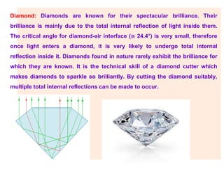
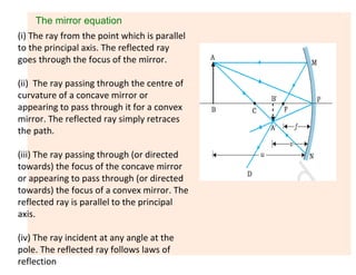
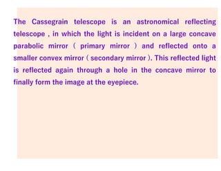
This document provides information about ray optics and optical instruments. It begins by defining key concepts in ray optics like reflection, refraction, total internal reflection, and dispersion. It then discusses these phenomena through examples like mirages, diamonds, and prisms. The document also covers topics in geometric optics like mirrors, lenses, the lens maker's formula, and optical instruments like microscopes and telescopes. It provides formulas for magnification, focal length, and angular magnification. In summary, the document is an overview of ray optics concepts and how they apply to the design and use of common optical instruments.

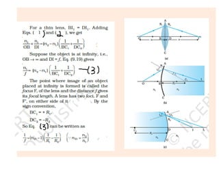
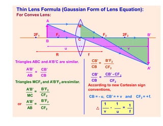
![Lens Maker’s Formula
The image formation can be seen in
terms of two steps:
(i) The first refracting surface forms
the image I1 of the object O
[Fig (b)].
The image I1 acts as a virtual object
for the second surface that forms
the image at I [Fig.(c].
For the first interface ABC, we get](https://image.slidesharecdn.com/rayoptics-230425160623-4a4af839/85/RAY-OPTICS-pdf-19-320.jpg)


![ANIMAL_CELL_,_TISSUE_AND_ORGAN_CULTURE[1].pptx](https://cdn.slidesharecdn.com/ss_thumbnails/animalcelltissueandorganculture1-260204172026-4462b440-thumbnail.jpg?width=640&height=640&fit=bounds)


