Downloaded 621 times


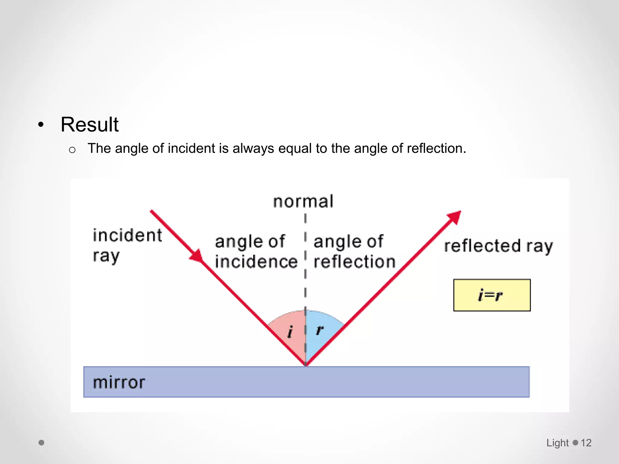


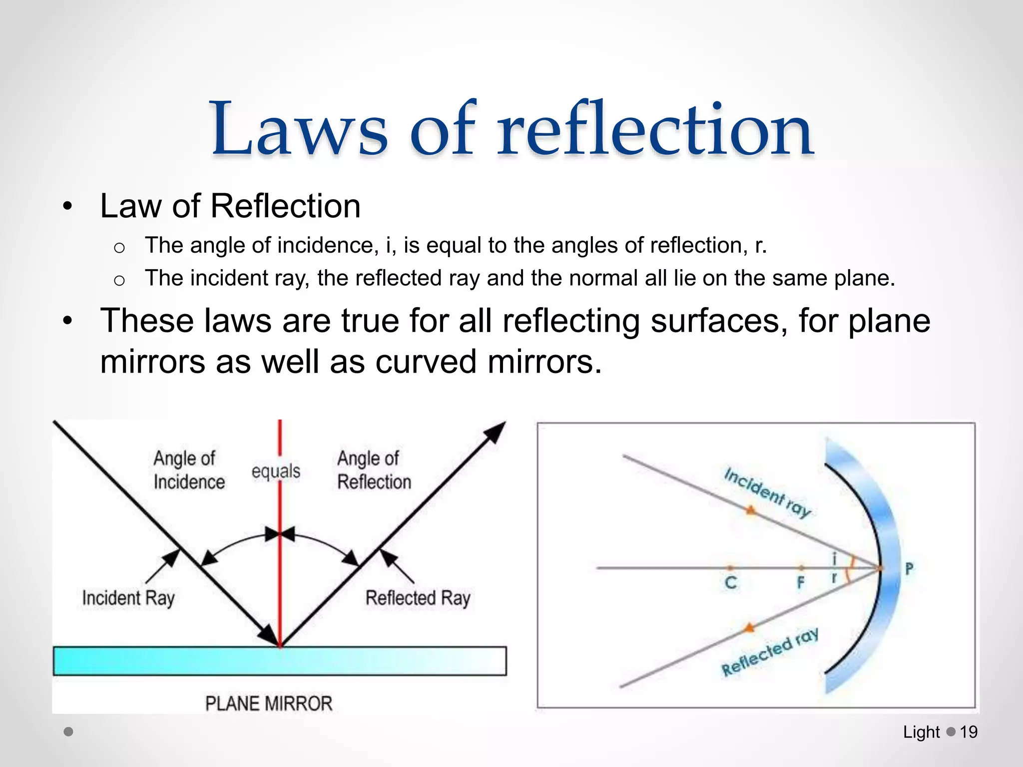


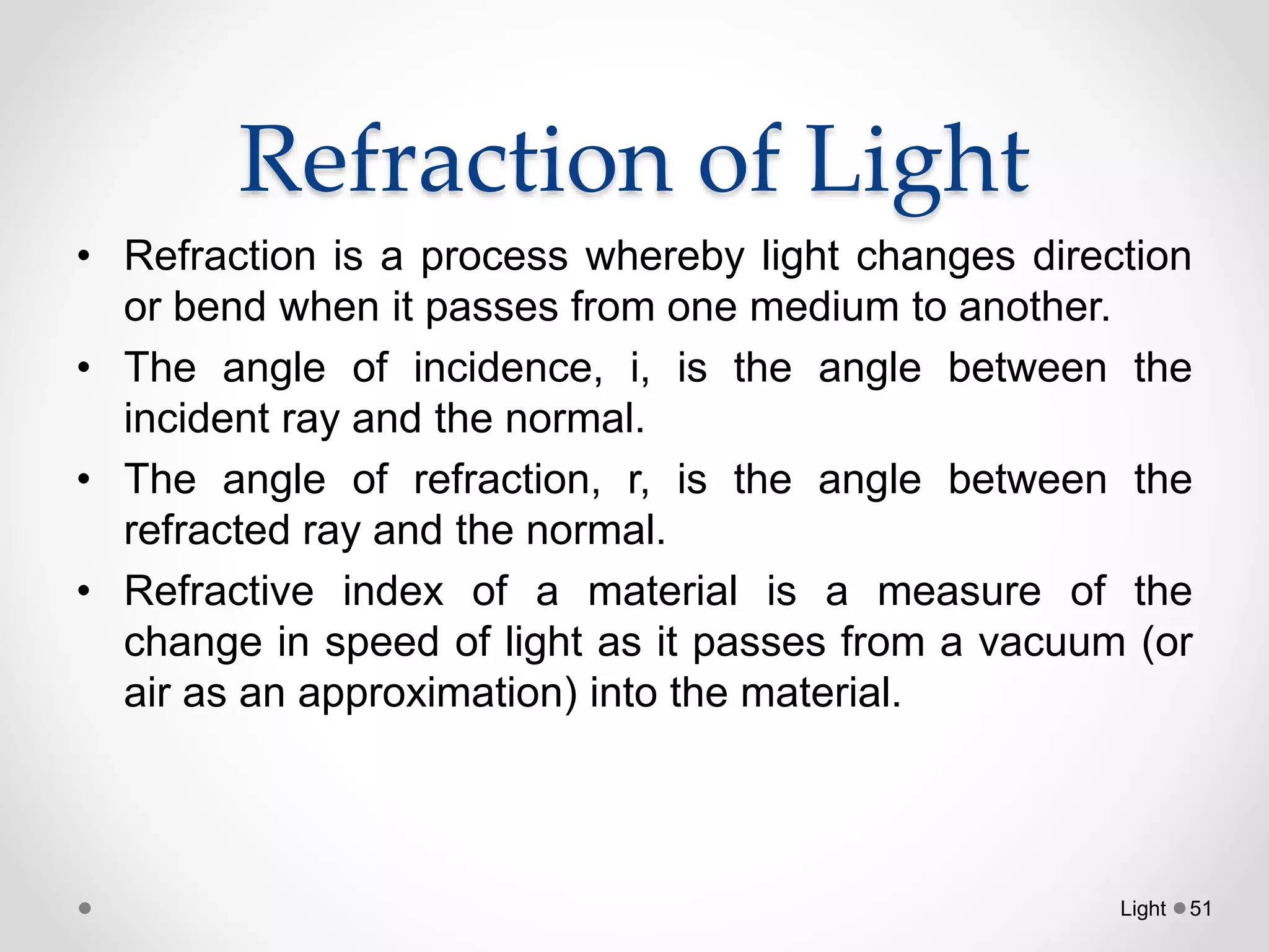


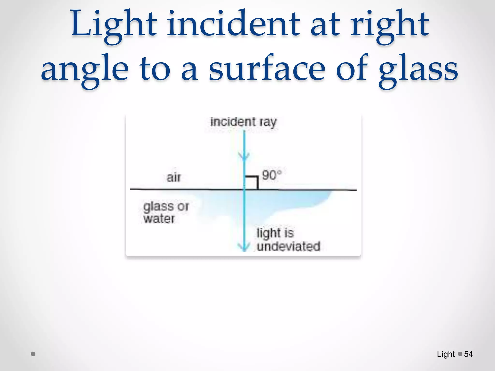


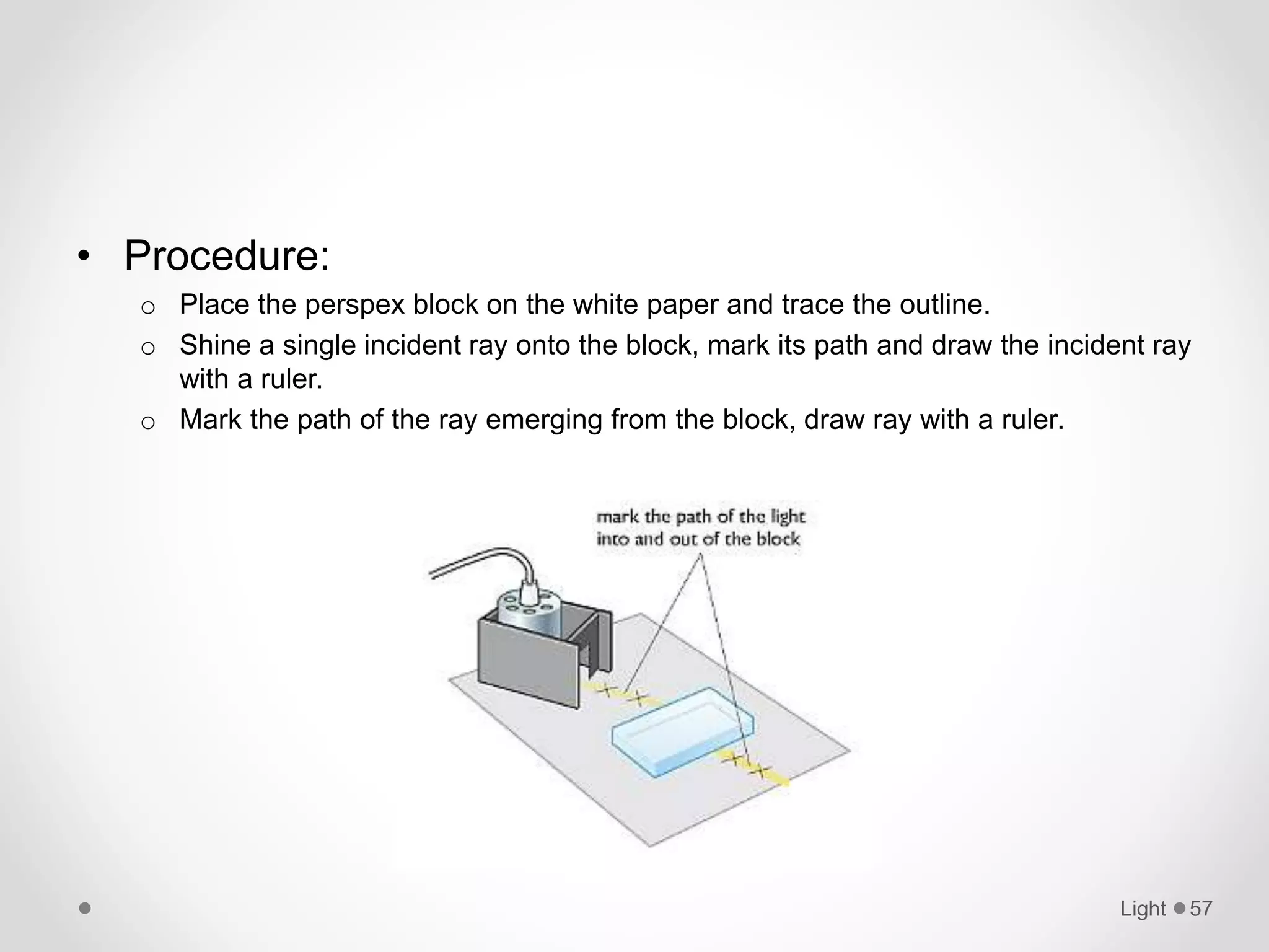

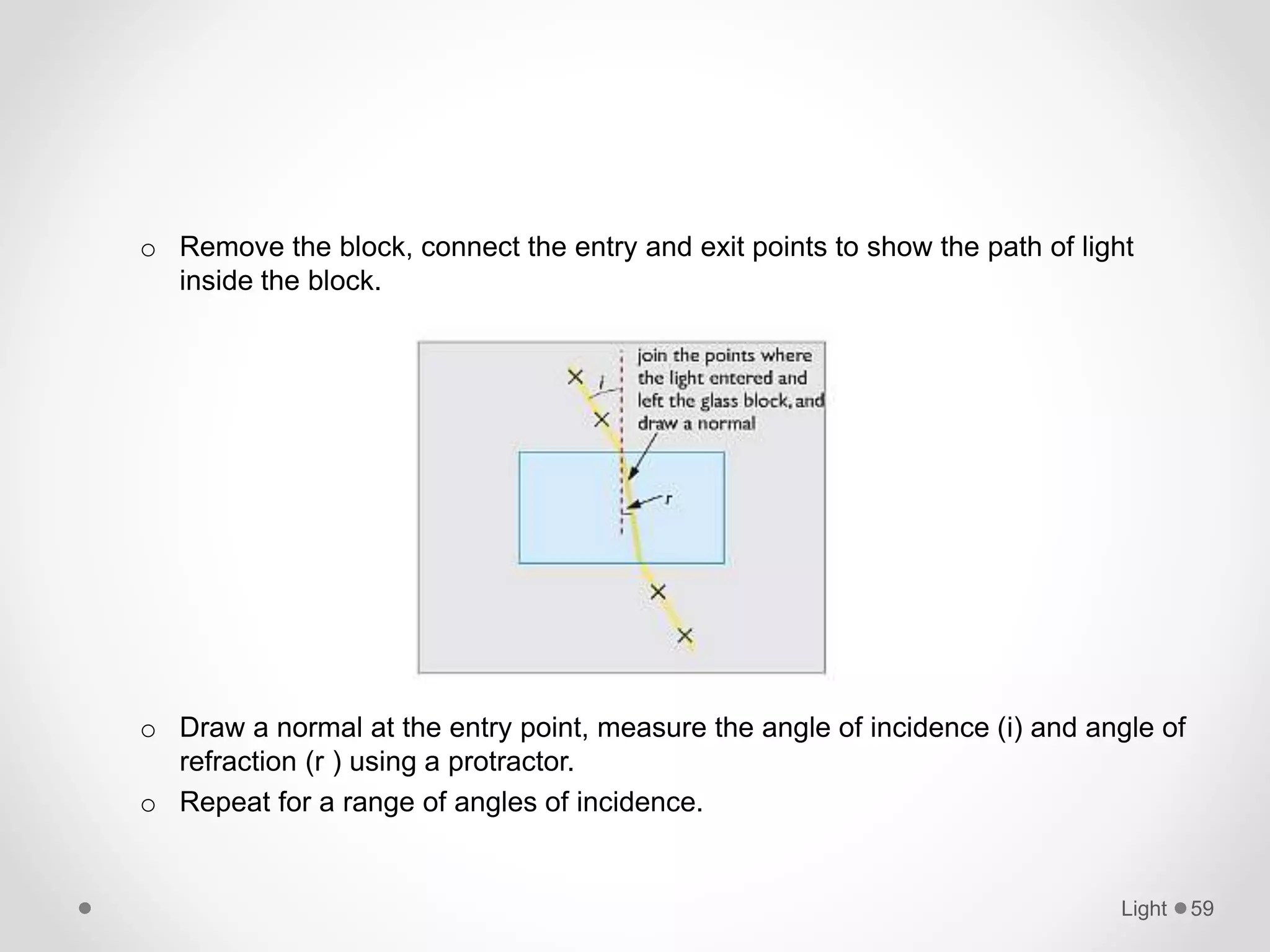


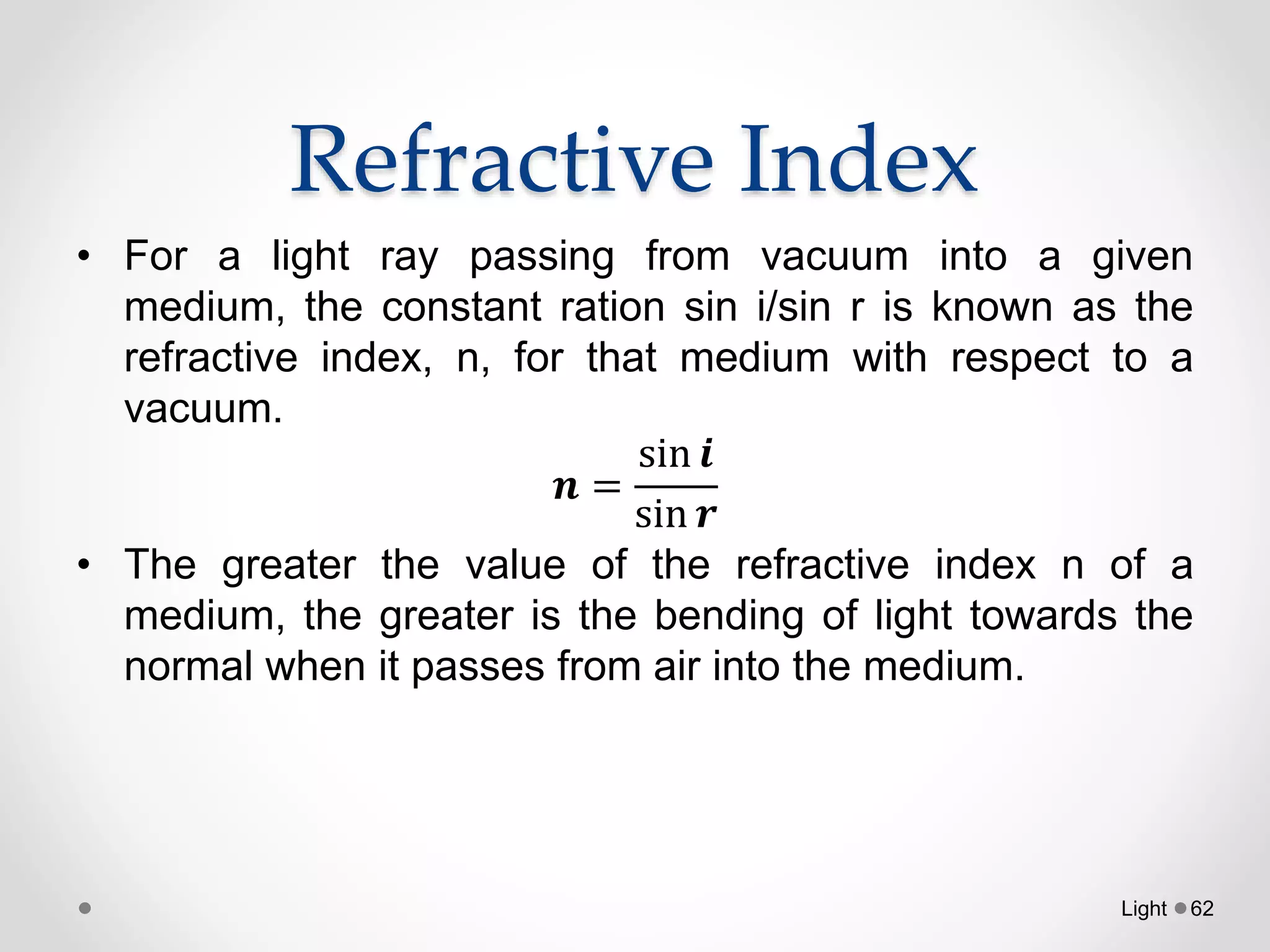


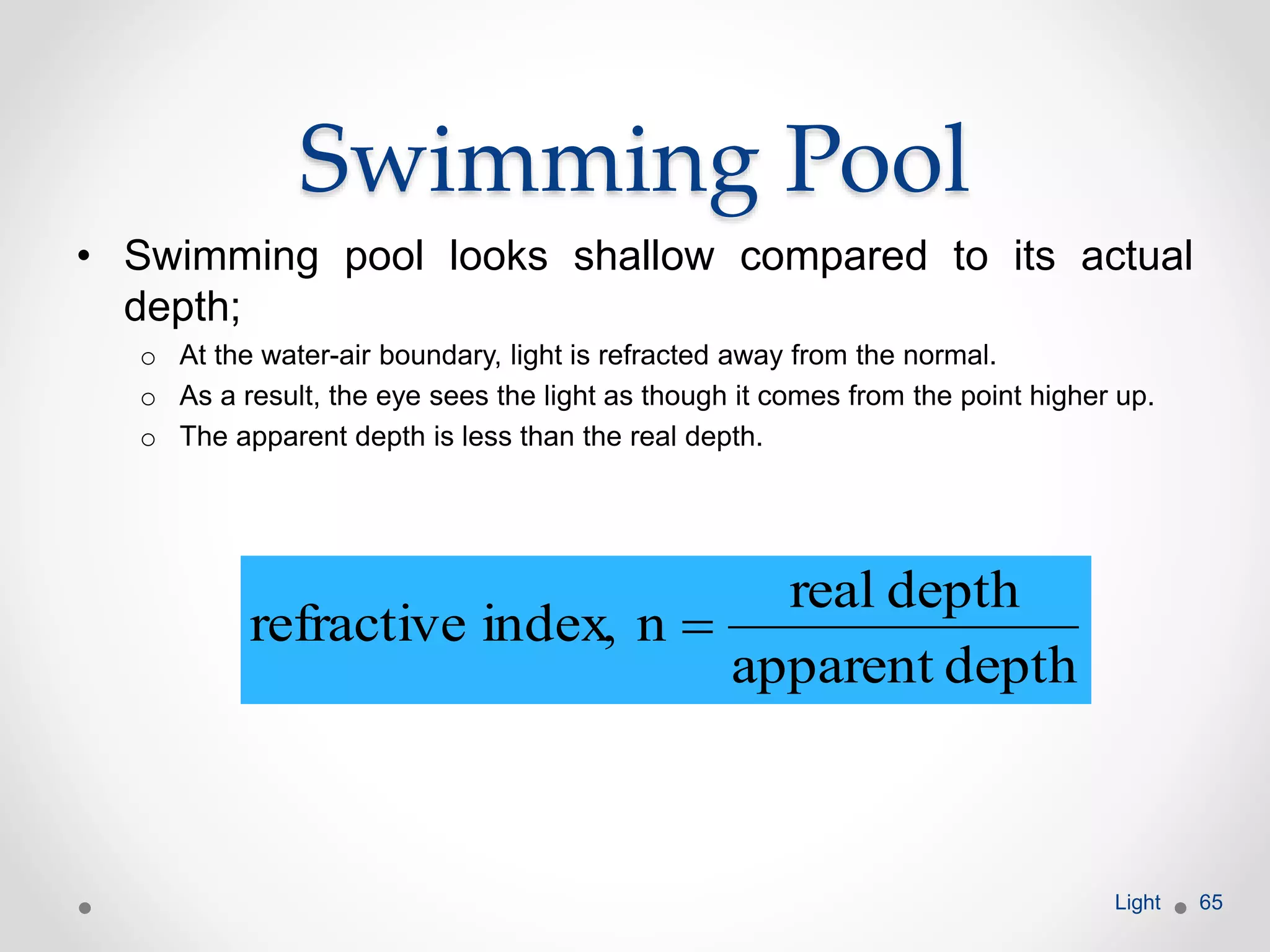


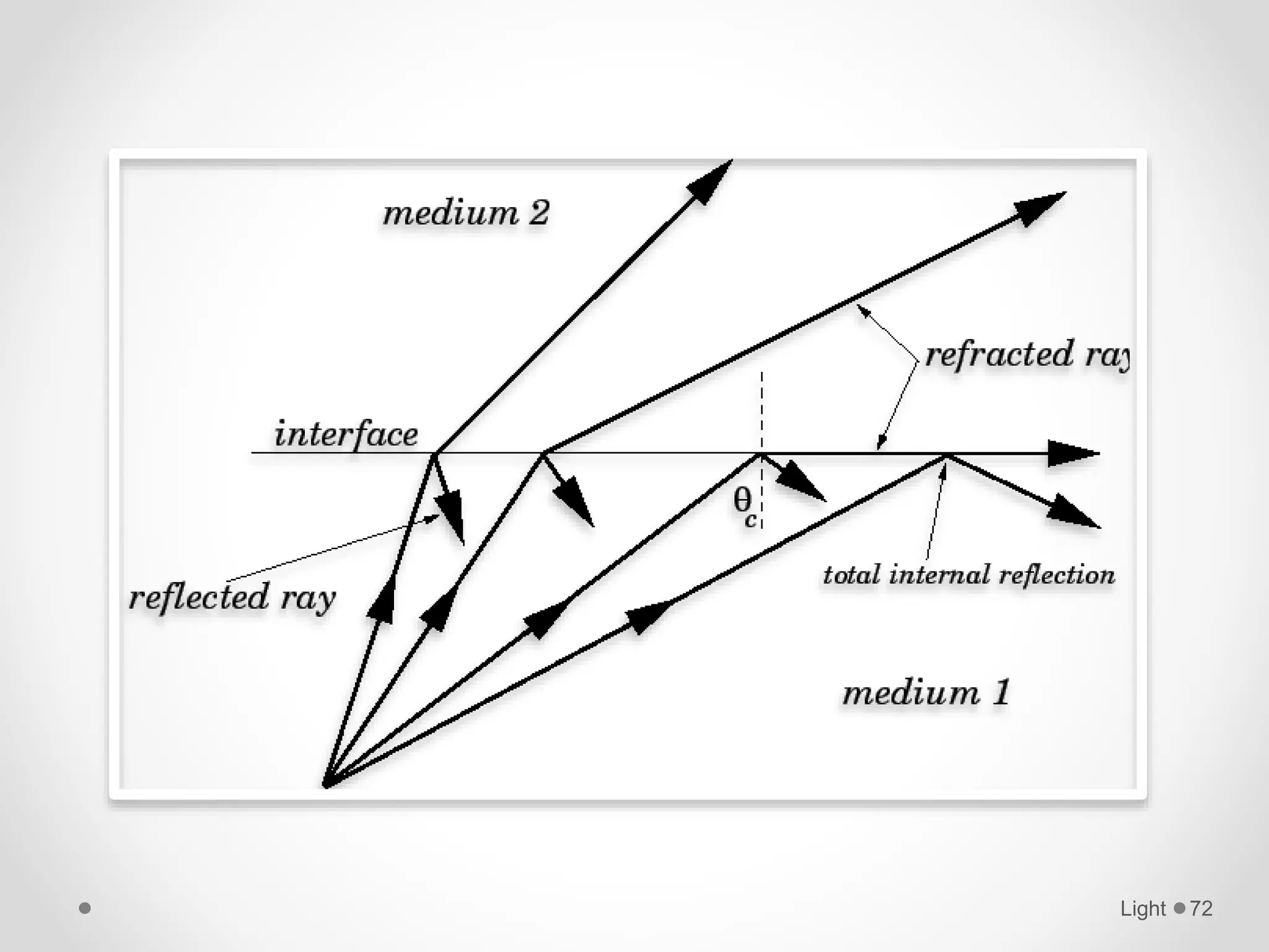


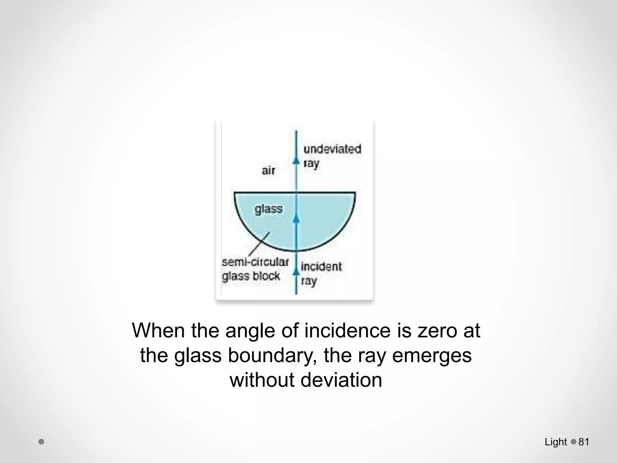


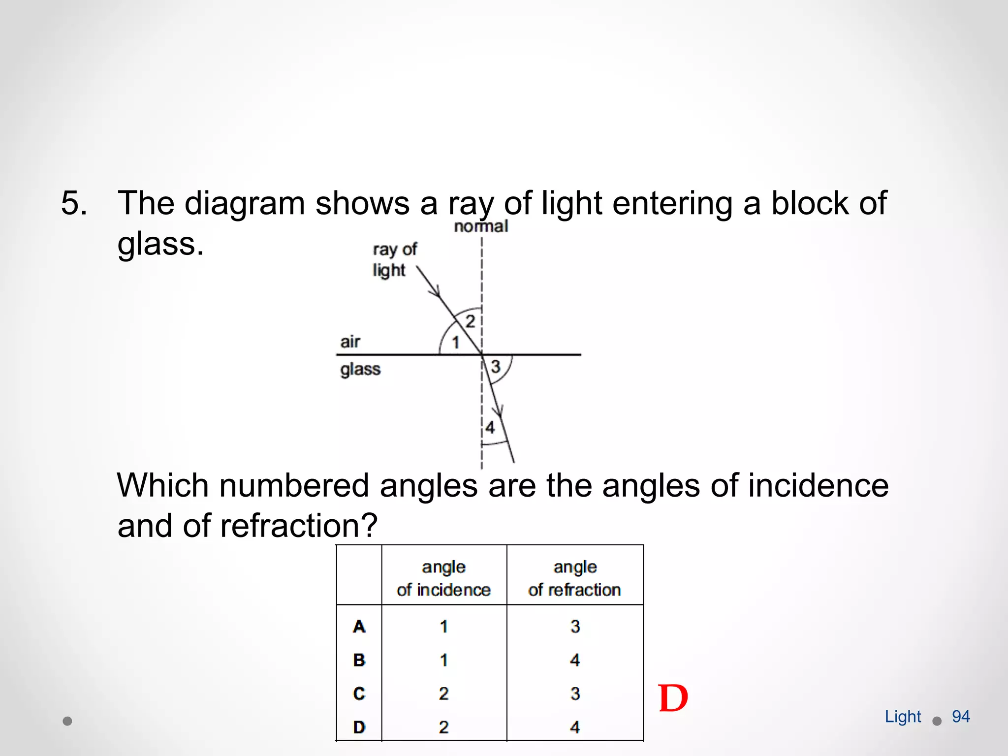
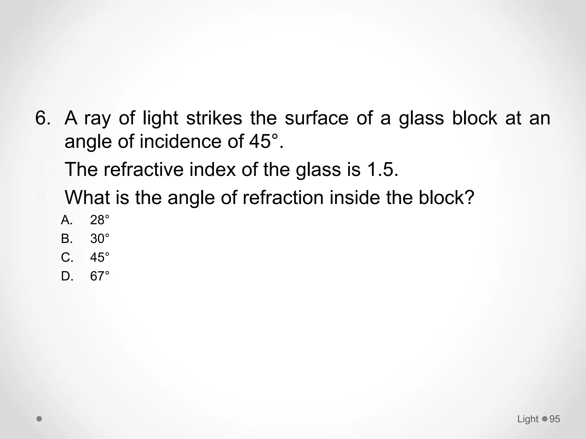

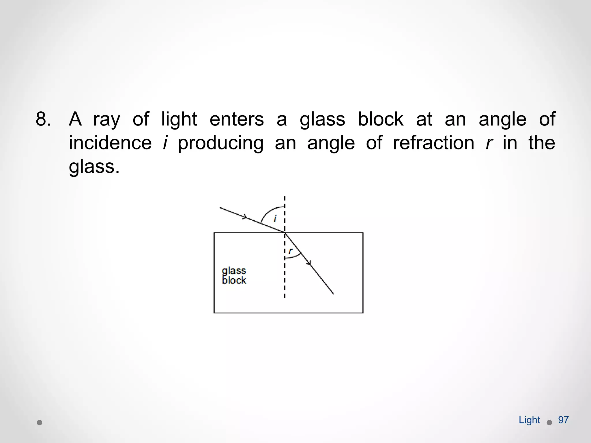


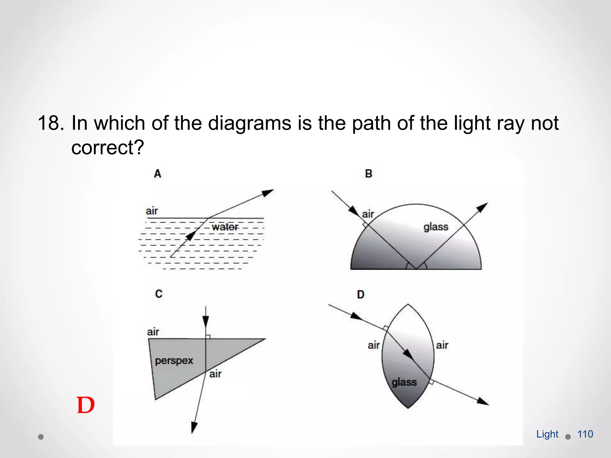


- Reflection of light occurs when light bounces off a surface. The angle of incidence is equal to the angle of reflection. - Refraction occurs when light changes speed and direction as it passes from one medium to another. The ratio of the sines of the angles of incidence and refraction is a constant value called the refractive index. - Experiments can show that light reflects according to the law of reflection and refracts at different angles depending on the medium, such as when passing through glass blocks. Measurements are used to determine refractive indices.


![[Unit 12.2] refraction of light](https://cdn.slidesharecdn.com/ss_thumbnails/unit12-2refractionoflight-100829070254-phpapp01-thumbnail.jpg?width=640&height=640&fit=bounds)


