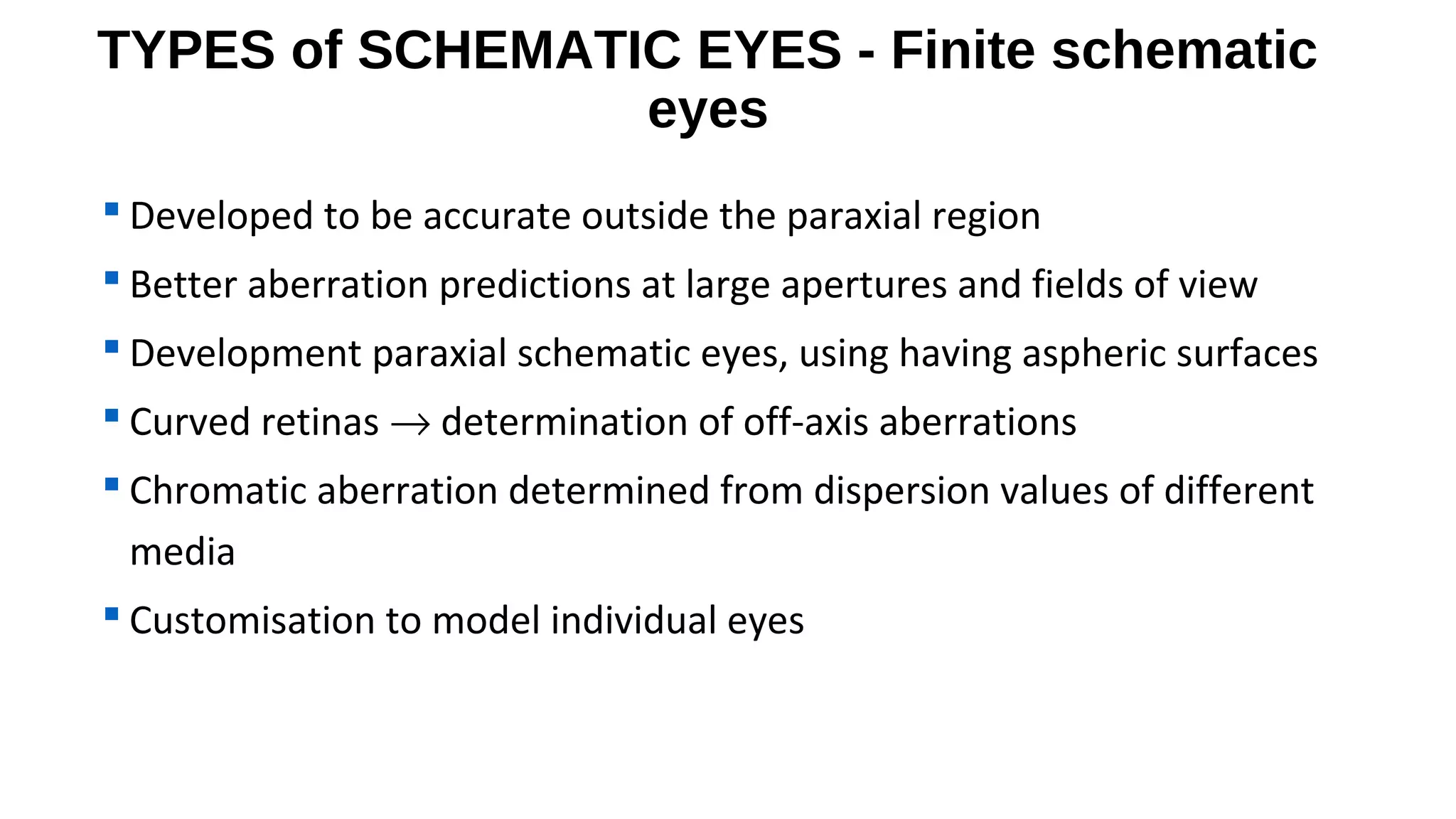
![Finite schematic eyes – conicoid
asphericity
• Simplest type of aspheric surface is conicoid
• Conic section rotated about its axis of
symmetry.
y
Q < -1
Q = -1
c[(x2 + y2) + z2 (1 + Q)] – 2z = 0
-1 < Q < 0
c is the vertex curvature of the surface and Q is
conic constant
Q=0
z
Q < –1 hyperboloid
Q = –1 paraboloid
–1 < Q < 0 flattening ellipsoid (prolate)
Q = 0 sphere
Q > 0 steepening ellipsoid (oblate)
x
Q>0](https://image.slidesharecdn.com/schematiceyeandcardinalpoints-140304085303-phpapp01/75/Schematic-eye-and-cardinal-points-15-2048.jpg)
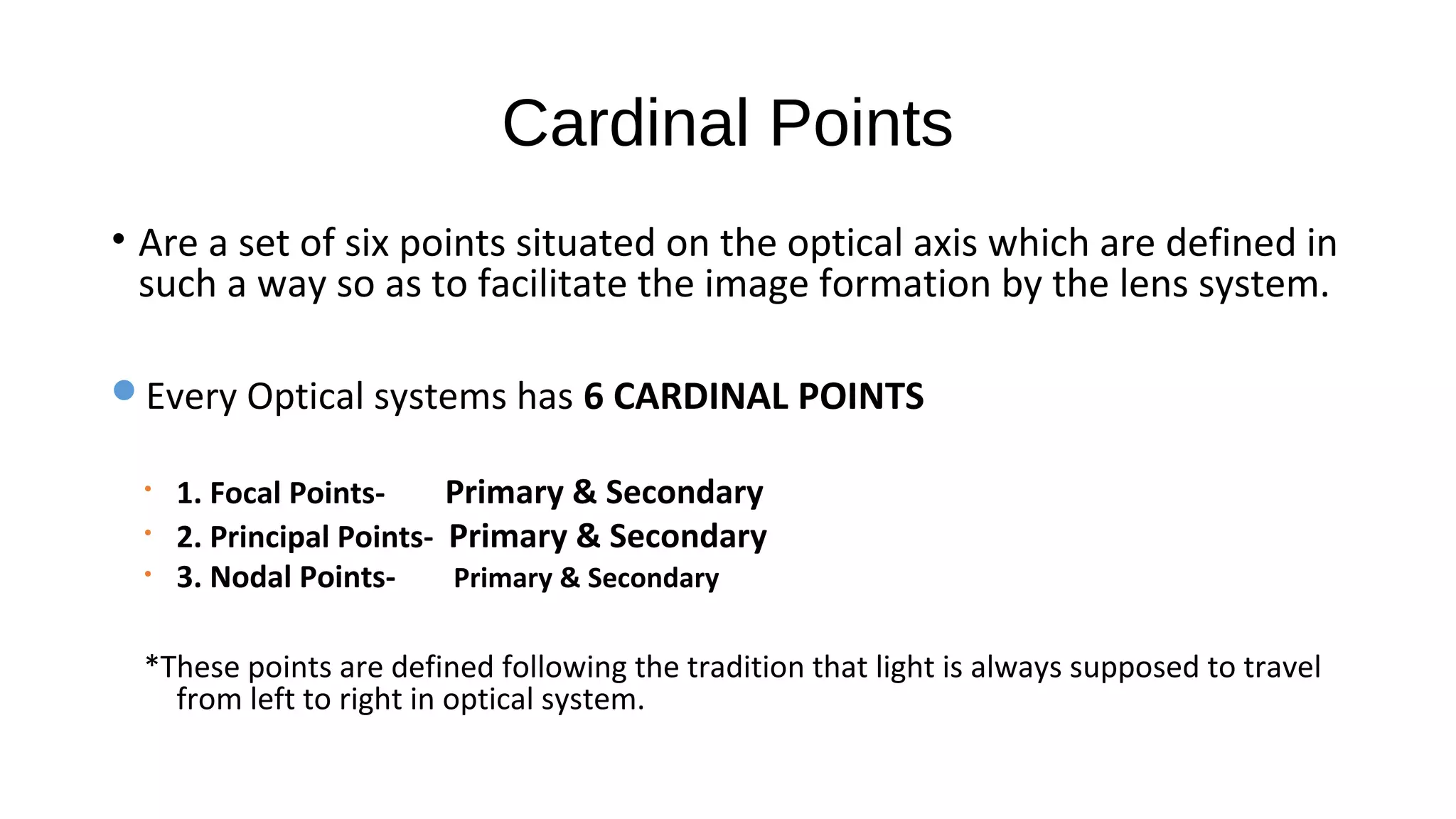
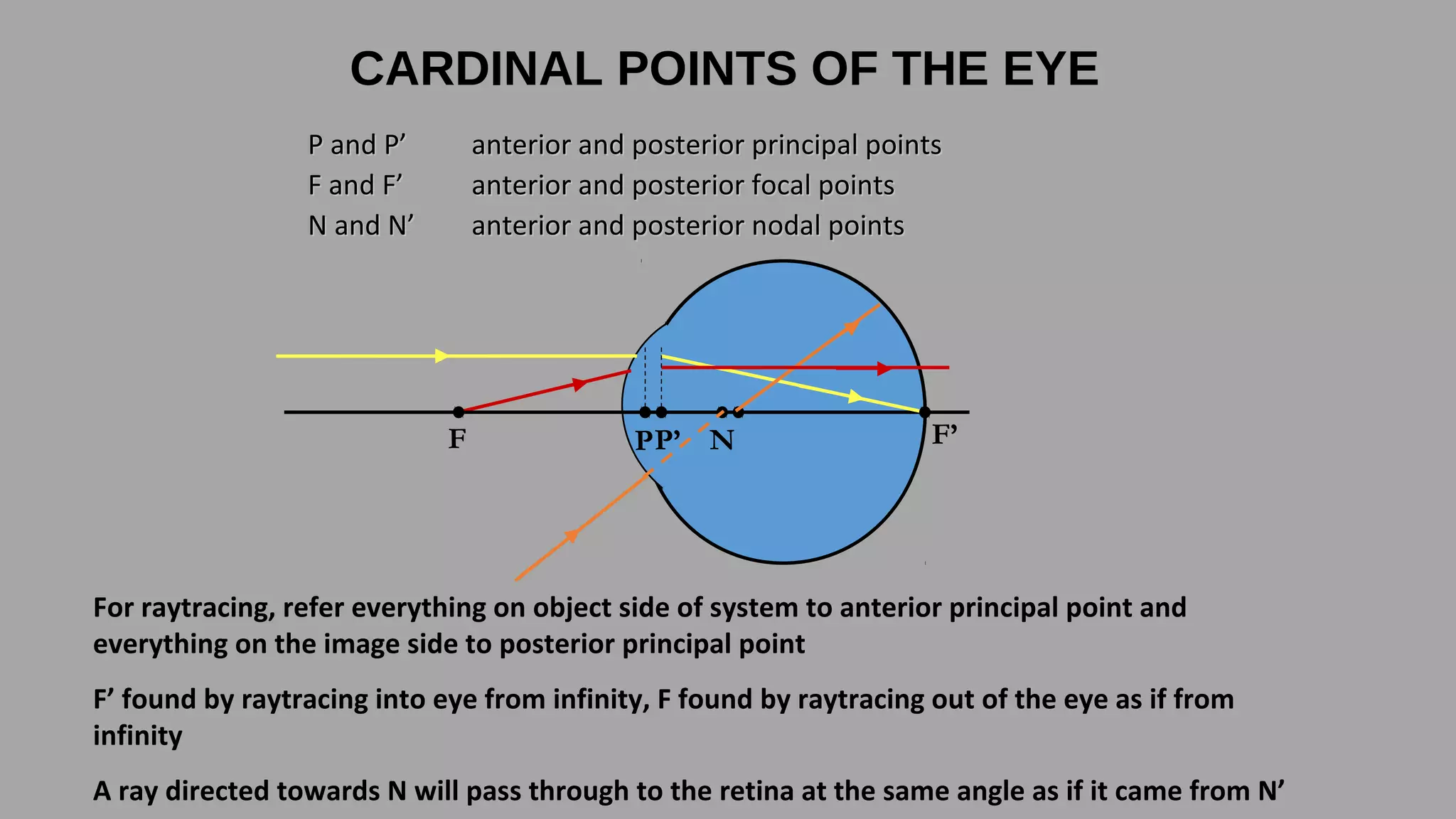

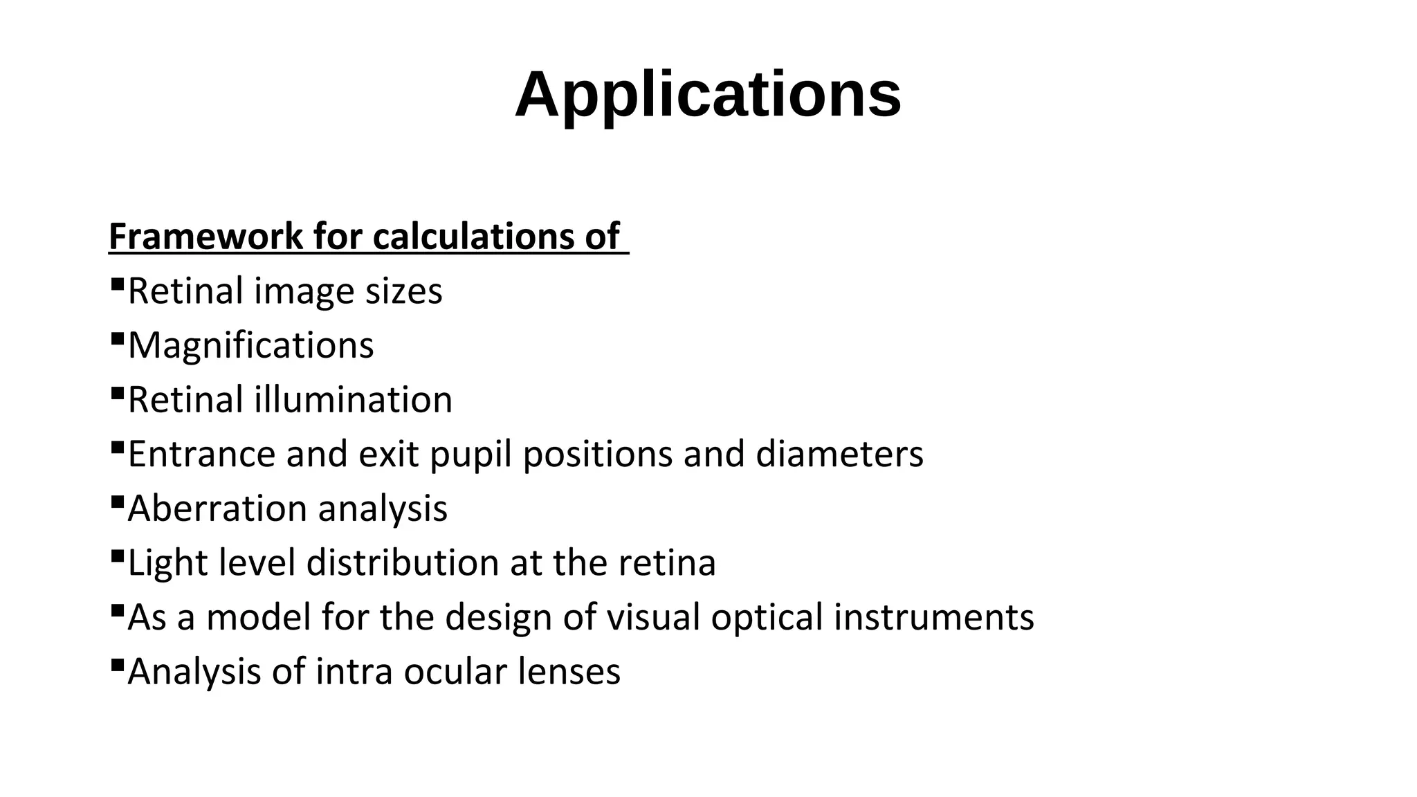
This document discusses schematic eyes and cardinal points. It provides an overview of different types of schematic eyes including paraxial and finite models. Paraxial eyes are simplified models useful for basic calculations while finite eyes are more accurate by including aspheric surfaces. The document also describes the six cardinal points - focal points, principal points, and nodal points - which define the optical properties and image formation of an eye. It explains how the locations of these points change under different conditions like aphakia. In summary, the document provides a comprehensive overview of schematic eye models and the important cardinal points used to analyze the optical performance of the eye.


