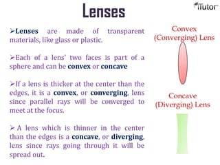
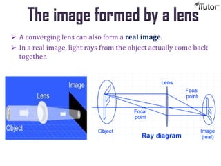
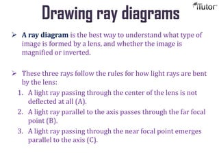
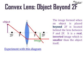
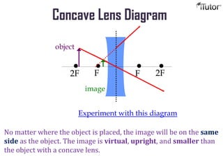
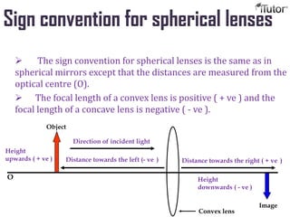
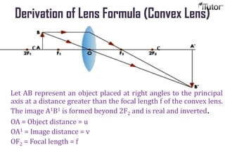
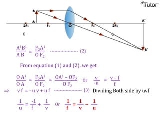
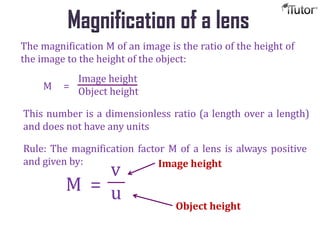
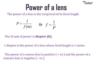
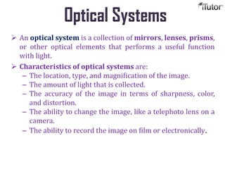
Lenses
T- 1-855-694-8886
Email- info@iTutor.com
By iTutor.com
Lenses
Lenses are made of transparent
materials, like glass or plastic.
Each of a lens’ two faces is part of a
sphere and can be convex or concave
If a lens is thicker at the center than the
edges, it is a convex, or converging, lens
since parallel rays will be converged to
meet at the focus.
 A lens which is thinner in the center
than the edges is a concave, or diverging,
lens since rays going through it will be
spread out.
Convex
(Converging) Lens
Concave
(Diverging) Lens
Lenses and Images
 Light rays that enter a converging lens parallel to its axis bend
to meet at a point called the focal point.
 The distance from the center of the lens to the focal point is
called the focal length.
 The optical axis usually goes through the center of the lens.
Focus of Lenses
The image formed by a lens
 A lens can form a virtual image just as a mirror does.
 Rays from the same point on an object are bent by the lens so
that they appear to come from a much larger object.
 A converging lens can also form a real image.
 In a real image, light rays from the object actually come back
together.
The image formed by a lens
Drawing ray diagrams
 A ray diagram is the best way to understand what type of
image is formed by a lens, and whether the image is
magnified or inverted.
 These three rays follow the rules for how light rays are bent
by the lens:
1. A light ray passing through the center of the lens is not
deflected at all (A).
2. A light ray parallel to the axis passes through the far focal
point (B).
3. A light ray passing through the near focal point emerges
parallel to the axis (C).
Convex Lens: Object Beyond 2F
•• • •F F 2F2F
object
image
The image formed when
an object is placed
beyond 2F is located
behind the lens between
F and 2F. It is a real,
inverted image which is
smaller than the object
itself.
Experiment with this diagram
Convex Lens: Object Between 2F and F
•• • •F F 2F2F
object
image
The image formed
when an object is
placed between 2F and
F is located beyond 2F
behind the lens. It is a
real, inverted image,
larger than the object.
Convex Lens: Object within F
•• • •F F 2F2F
object
image
The image formed when an object is placed in front of F is
located somewhere beyond F on the same side of the lens as
the object. It is a virtual, upright image which is larger than
the object.
convex lens used as a magnifier
Concave Lens Diagram
•• • •F F 2F2F
object
image
No matter where the object is placed, the image will be on the same
side as the object. The image is virtual, upright, and smaller than
the object with a concave lens.
Experiment with this diagram
Sign convention for spherical lenses
 The sign convention for spherical lenses is the same as in
spherical mirrors except that the distances are measured from the
optical centre (O).
 The focal length of a convex lens is positive ( + ve ) and the
focal length of a concave lens is negative ( - ve ).
Direction of incident light
Distance towards the left (- ve )
Height
downwards ( - ve )
Height
upwards ( + ve )
Convex lens
Object
Image
O
Distance towards the right ( + ve )
Thin lens formula
 The thin lens formula is a mathematical way to do ray
diagrams with algebra instead of drawing lines on graph
paper.
1 + 1 = 1
o i f
focal
length (cm)
Image distance
(cm)
Object
distance
(cm)
Thin lens formula
Derivation of Lens Formula (Convex Lens)
Let AB represent an object placed at right angles to the principal
axis at a distance greater than the focal length f of the convex lens.
The image A1B1 is formed beyond 2F2 and is real and inverted.
OA = Object distance = u
OA1 = Image distance = v
OF2 = Focal length = f
C C
OAB and OA1B1 are similar
A1B1
A B
=
O A1
O A
------------------- (1)
Similarly , OCF2 and F2A1B1 are similar
A1B1
O C
=
F2A1
O F2
C C
But we know that OC = AB
the above equation can be written as
C C
A1B1
A B
=
F2A1
O F2
------------------- (2)
From equation (1) and (2), we get
O A1
O A
= F2A1
O F2
= OA1 – OF2
O F2
v
-u
= v – f
f
Or
v f = - u v + u f ------------------- (3) Dividing Both side by uvf
1
u
=
-1
f
+
1
v
Or
1
f
=
1
v
1
u
–
The magnification M of an image is the ratio of the height of
the image to the height of the object:
M =
Image height
Object height
This number is a dimensionless ratio (a length over a length)
and does not have any units
Rule: The magnification factor M of a lens is always positive
and given by:
M =
v
u
Image height
Object height
Magnification of a lens
Power of a lens
The power of a lens is the reciprocal of its focal length
The SI unit of power is dioptre (D).
1 dioptre is the power of a lens whose focal length is 1 meter.
The power of a convex lens is positive ( + ve ) and the power of a
concave lens is negative ( - ve ).
)(
1
mf
P
P
f
1
0r
Optical Systems
 An optical system is a collection of mirrors, lenses, prisms,
or other optical elements that performs a useful function
with light.
 Characteristics of optical systems are:
– The location, type, and magnification of the image.
– The amount of light that is collected.
– The accuracy of the image in terms of sharpness, color,
and distortion.
– The ability to change the image, like a telephoto lens on a
camera.
– The ability to record the image on film or electronically.
Call us for more
Information:
www.iTutor.com
1-855-694-8886
Visit
The End

Lenses

  • 1.
  • 2.
    Lenses Lenses are madeof transparent materials, like glass or plastic. Each of a lens’ two faces is part of a sphere and can be convex or concave If a lens is thicker at the center than the edges, it is a convex, or converging, lens since parallel rays will be converged to meet at the focus.  A lens which is thinner in the center than the edges is a concave, or diverging, lens since rays going through it will be spread out. Convex (Converging) Lens Concave (Diverging) Lens
  • 3.
    Lenses and Images Light rays that enter a converging lens parallel to its axis bend to meet at a point called the focal point.  The distance from the center of the lens to the focal point is called the focal length.  The optical axis usually goes through the center of the lens.
  • 4.
  • 5.
    The image formedby a lens  A lens can form a virtual image just as a mirror does.  Rays from the same point on an object are bent by the lens so that they appear to come from a much larger object.
  • 6.
     A converginglens can also form a real image.  In a real image, light rays from the object actually come back together. The image formed by a lens
  • 7.
    Drawing ray diagrams A ray diagram is the best way to understand what type of image is formed by a lens, and whether the image is magnified or inverted.  These three rays follow the rules for how light rays are bent by the lens: 1. A light ray passing through the center of the lens is not deflected at all (A). 2. A light ray parallel to the axis passes through the far focal point (B). 3. A light ray passing through the near focal point emerges parallel to the axis (C).
  • 8.
    Convex Lens: ObjectBeyond 2F •• • •F F 2F2F object image The image formed when an object is placed beyond 2F is located behind the lens between F and 2F. It is a real, inverted image which is smaller than the object itself. Experiment with this diagram
  • 9.
    Convex Lens: ObjectBetween 2F and F •• • •F F 2F2F object image The image formed when an object is placed between 2F and F is located beyond 2F behind the lens. It is a real, inverted image, larger than the object.
  • 10.
    Convex Lens: Objectwithin F •• • •F F 2F2F object image The image formed when an object is placed in front of F is located somewhere beyond F on the same side of the lens as the object. It is a virtual, upright image which is larger than the object. convex lens used as a magnifier
  • 11.
    Concave Lens Diagram ••• •F F 2F2F object image No matter where the object is placed, the image will be on the same side as the object. The image is virtual, upright, and smaller than the object with a concave lens. Experiment with this diagram
  • 12.
    Sign convention forspherical lenses  The sign convention for spherical lenses is the same as in spherical mirrors except that the distances are measured from the optical centre (O).  The focal length of a convex lens is positive ( + ve ) and the focal length of a concave lens is negative ( - ve ). Direction of incident light Distance towards the left (- ve ) Height downwards ( - ve ) Height upwards ( + ve ) Convex lens Object Image O Distance towards the right ( + ve )
  • 13.
    Thin lens formula The thin lens formula is a mathematical way to do ray diagrams with algebra instead of drawing lines on graph paper. 1 + 1 = 1 o i f focal length (cm) Image distance (cm) Object distance (cm)
  • 14.
  • 15.
    Derivation of LensFormula (Convex Lens) Let AB represent an object placed at right angles to the principal axis at a distance greater than the focal length f of the convex lens. The image A1B1 is formed beyond 2F2 and is real and inverted. OA = Object distance = u OA1 = Image distance = v OF2 = Focal length = f C C
  • 16.
    OAB and OA1B1are similar A1B1 A B = O A1 O A ------------------- (1) Similarly , OCF2 and F2A1B1 are similar A1B1 O C = F2A1 O F2 C C But we know that OC = AB the above equation can be written as
  • 17.
    C C A1B1 A B = F2A1 OF2 ------------------- (2) From equation (1) and (2), we get O A1 O A = F2A1 O F2 = OA1 – OF2 O F2 v -u = v – f f Or v f = - u v + u f ------------------- (3) Dividing Both side by uvf 1 u = -1 f + 1 v Or 1 f = 1 v 1 u –
  • 18.
    The magnification Mof an image is the ratio of the height of the image to the height of the object: M = Image height Object height This number is a dimensionless ratio (a length over a length) and does not have any units Rule: The magnification factor M of a lens is always positive and given by: M = v u Image height Object height Magnification of a lens
  • 19.
    Power of alens The power of a lens is the reciprocal of its focal length The SI unit of power is dioptre (D). 1 dioptre is the power of a lens whose focal length is 1 meter. The power of a convex lens is positive ( + ve ) and the power of a concave lens is negative ( - ve ). )( 1 mf P P f 1 0r
  • 20.
    Optical Systems  Anoptical system is a collection of mirrors, lenses, prisms, or other optical elements that performs a useful function with light.  Characteristics of optical systems are: – The location, type, and magnification of the image. – The amount of light that is collected. – The accuracy of the image in terms of sharpness, color, and distortion. – The ability to change the image, like a telephoto lens on a camera. – The ability to record the image on film or electronically.
  • 21.
    Call us formore Information: www.iTutor.com 1-855-694-8886 Visit The End