Downloaded 1,168 times

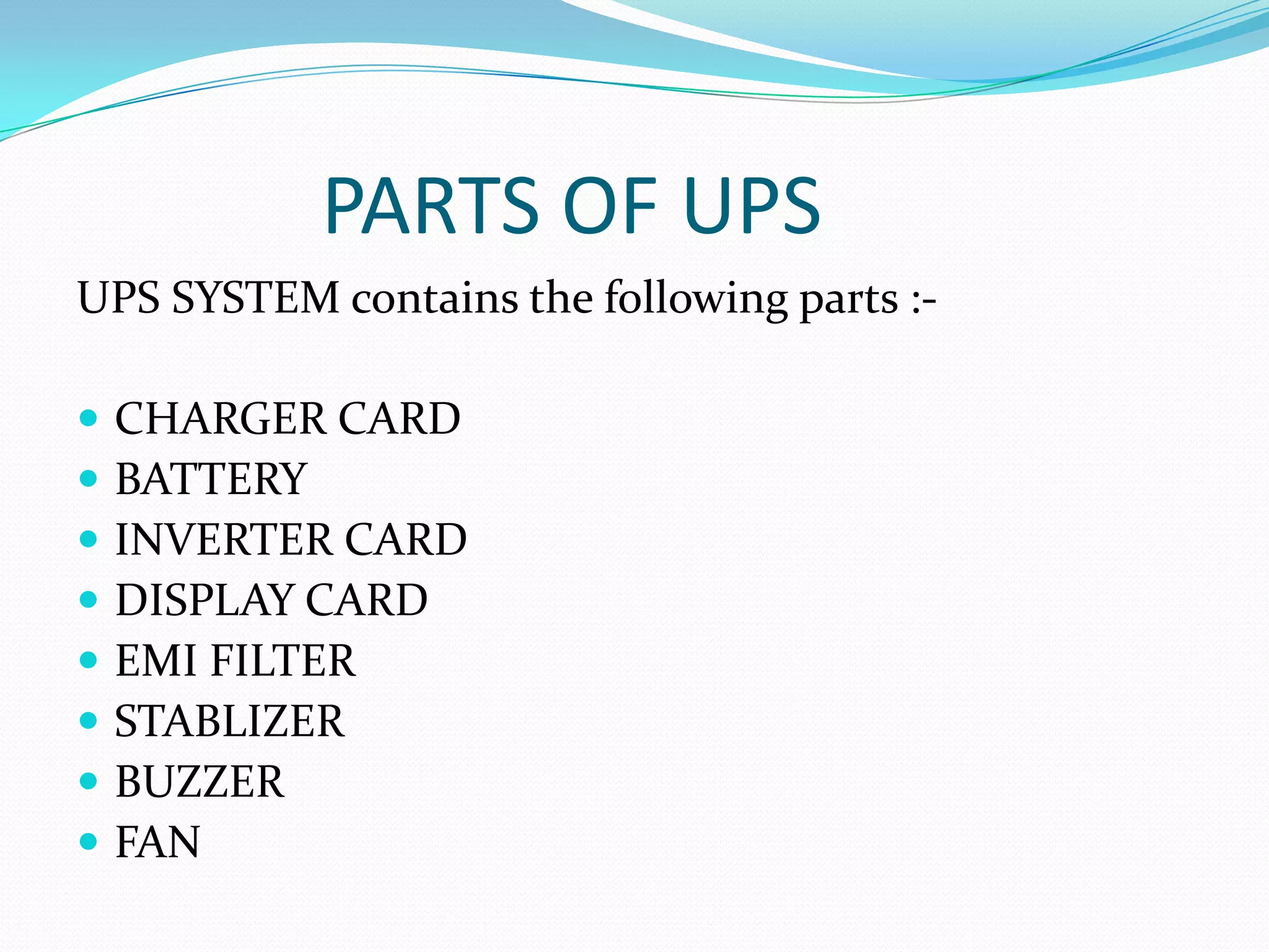
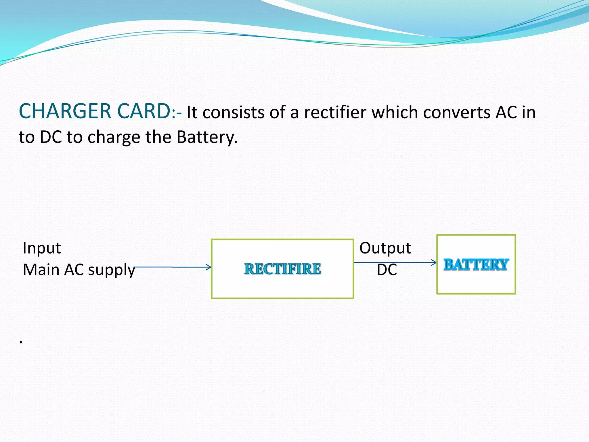
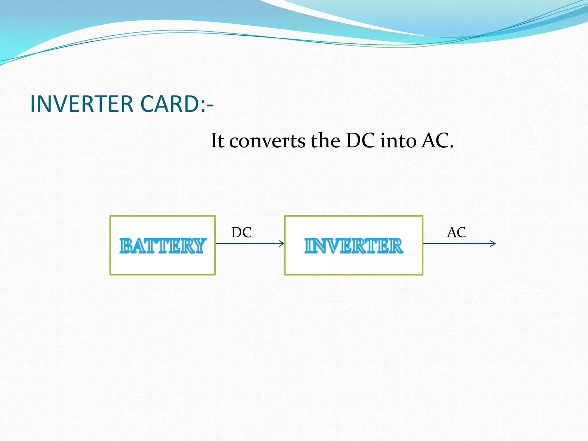
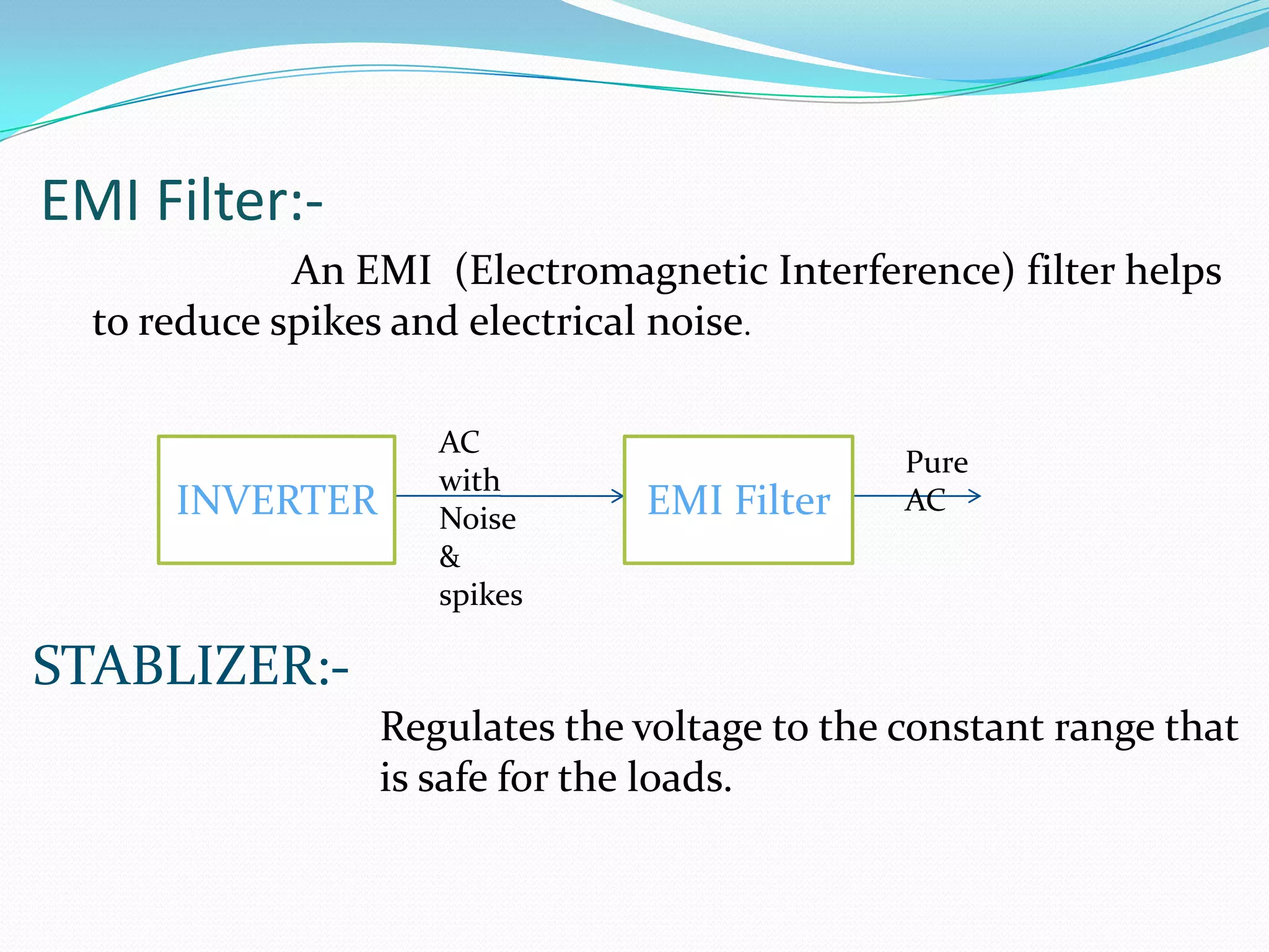
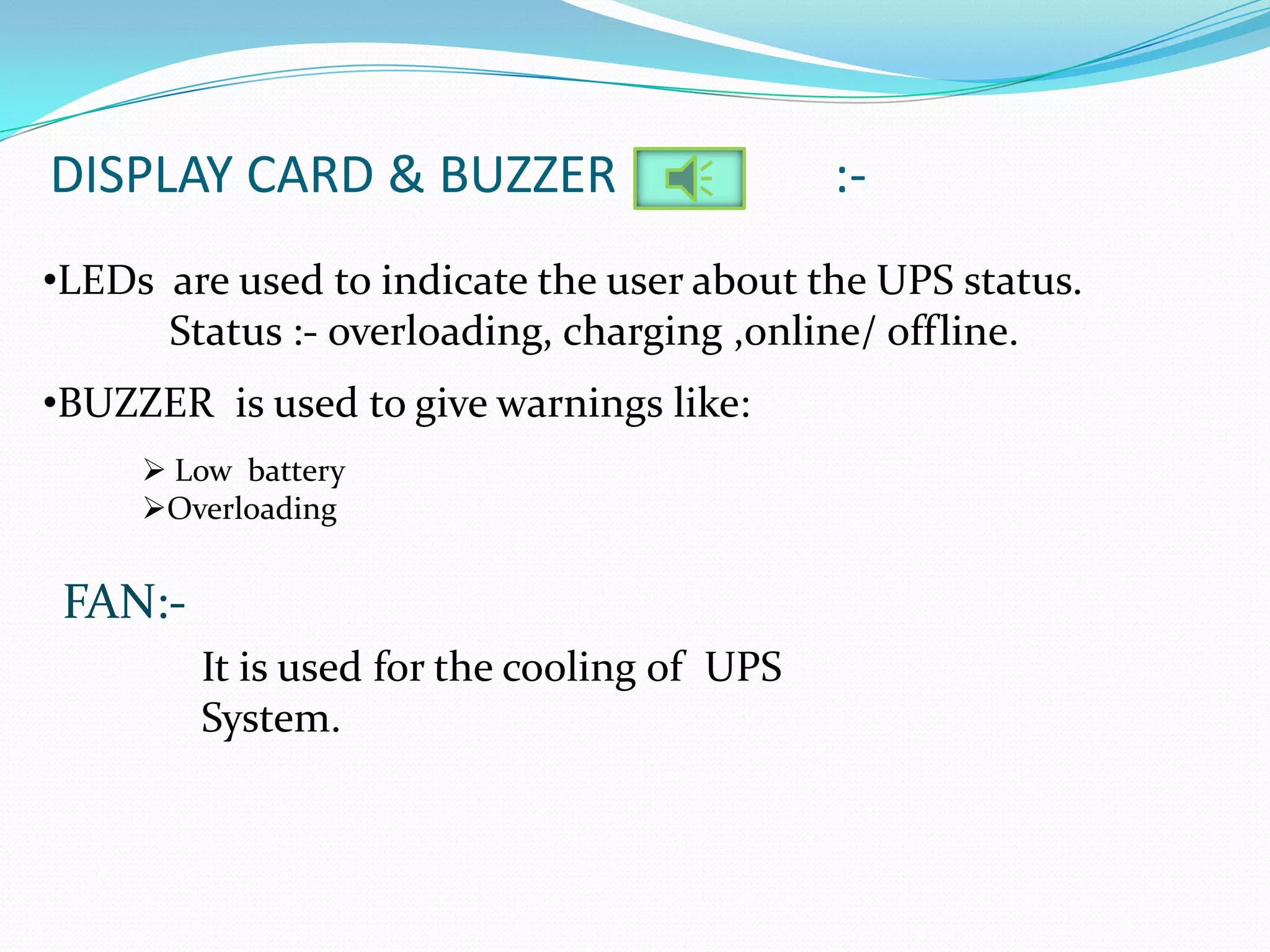
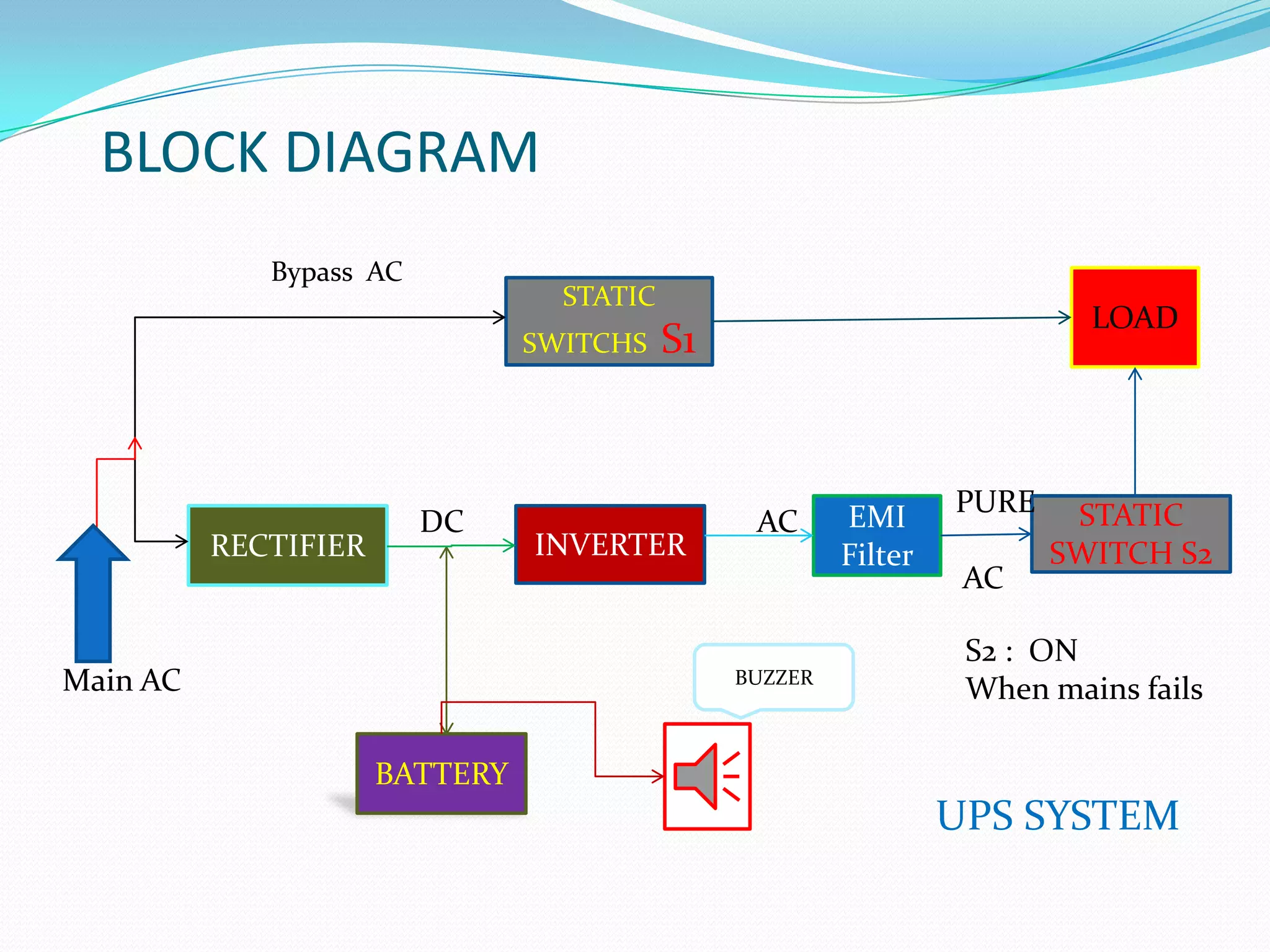

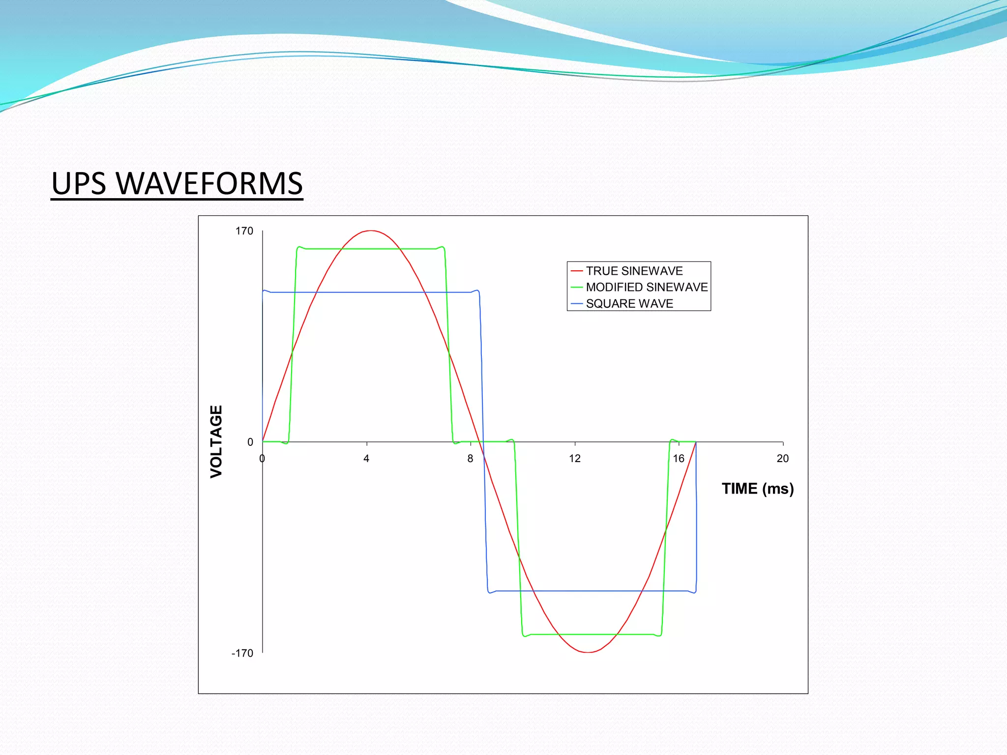
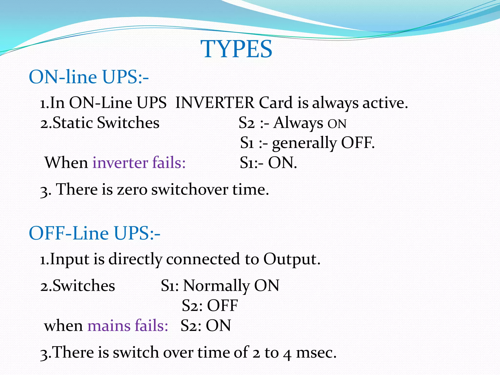
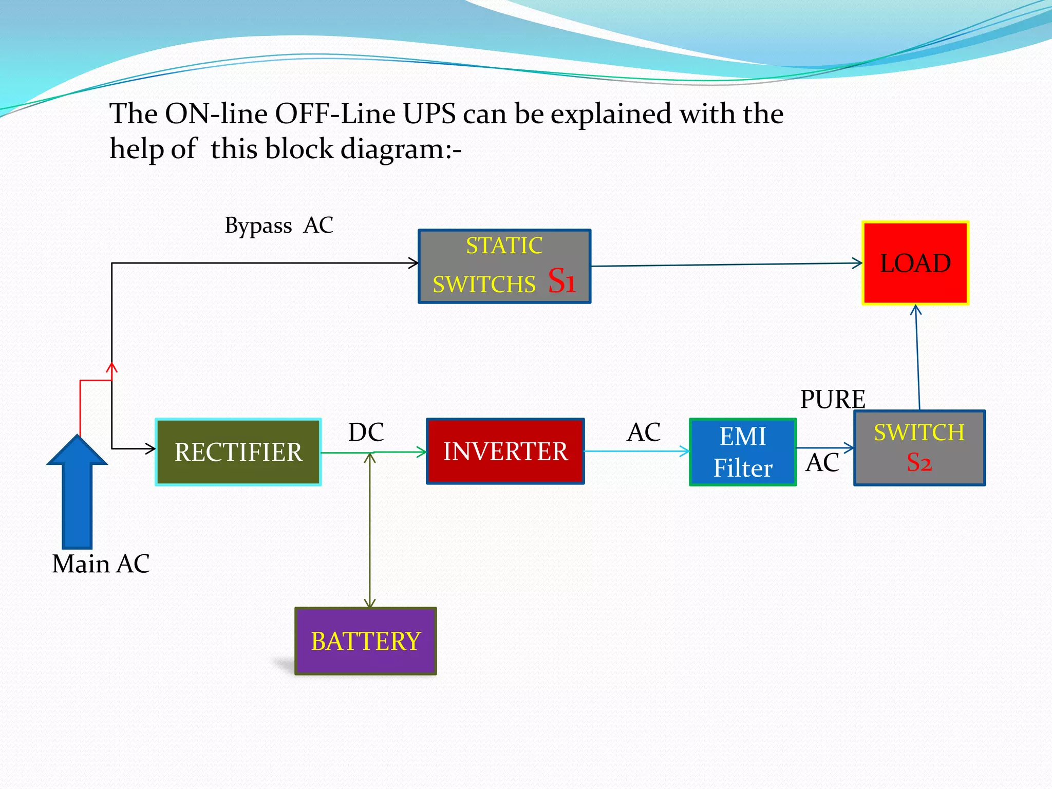
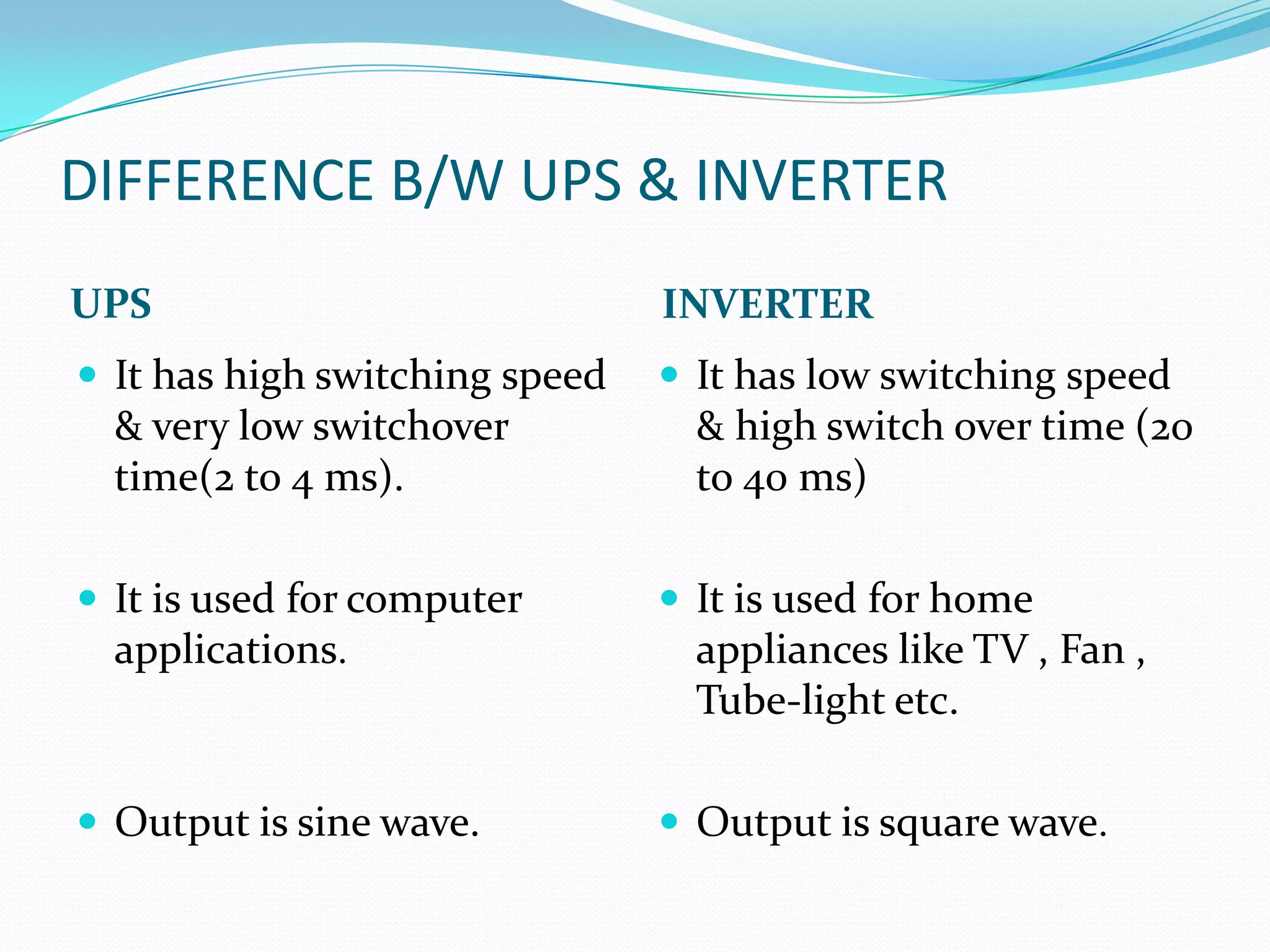


This document provides an overview of an uninterruptible power supply (UPS) system. It describes the key parts of a UPS including the charger card, battery, inverter card, and display card. It also includes block diagrams that show how the different components work together. The document discusses the different types of UPS systems, common output waveforms, applications of UPS systems, and key differences between UPS and inverter systems.


