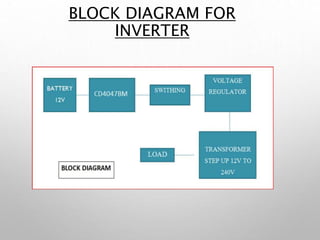
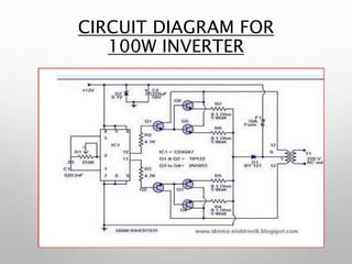
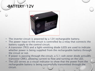
MINI INVERTER 12V TO
220V
GUIDEDBY: DR MARY VINAYA PRESENTED BY: ADHEENA.V.S
PERSIS ABEY
SHAMLA.K
OBJECTIVE
To convert a 12V DC power supply into a 240V AC output
using a transformer to step up the power to upto 1KW
MINI INVERTER
• It is a dc-to-ac power inverters which aim to efficiently transform
a DC power source into a high-voltage AC source similar to the
power that would be available at an electrical wall outlet.
• Inverters are used for many applications, s
• s in situations where low-voltage DC sources such as batteries, solar
panels, or fuel cells must be converted so that devices can run off of
AC power. One example of such a situation would be converting
electrical power from a car battery to run a laptop, TV, or cell phone.
WORKING PROCESS
1. The 100-watt inverter circuit uses a CD 4047 IC as an astable
multivibrator to generate two 180-degree out-of-phase 100 HZ pulse
trains.
2.The pulse trains are pre-amplified by two TIP122 transistors.
3.The pre-amplified signals are further amplified by four 2n3055
transistors, with two transistors used for each half cycle.
4.The amplified signals are used to drive an inverter transformer,
producing a 220v ac output at the transformer's secondary.
BLOCK DIAGRAM FOR
INVERTER
CIRCUIT DIAGRAM FOR
100W INVERTER
COMPONENTS
• CD4047BC
• BATTERY12V
• TRANSISTOR 1) TIP 122 2) TIP 3055
• PLUG5A
• SWITCH MCB
• TRANSFORMER(STEPUP)
• RESISTOR
• DIODE
• VARIABLEPORT(250K)
• CAPACITOR FUSE(10A)
• WIRES
• CMOS PLASTIC PACKAGE DIODE
• HEATSINK
COMPONENT DISCRIPTION
•CD4047BC
• The CD4047B IC can operate in mono-stable or
a-stable modes.
• In mono-stable mode, an external capacitor
and resistor are used to control the output
pulse width.
• In a-stable mode, the output frequency is
determined by the external timing components.
• A-stable operation is enabled by a high level
on the a-stable input or a low level on the
mono-stable input.
• The Q and Q outputs provide a frequency
determined by the timing components, while
the oscillator output offers double the
frequency of Q with an unspecified duty cycle.
•PLUG SOCKET
• The ring circuit system, also known as "ring main," is used to provide
a single-phase electrical supply for running single-phase motors.
• In a ring circuit, instead of individually wiring each socket, a cable is
brought from the distribution board and connected in sequence to
multiple sockets before returning to the distribution board and being
connected to the same fuse or circuit breaker.
• This setup results in significant copper savings in the wiring of the
circuit.
• The fuse or circuit breaker used in the distribution board must be
rated for the maximum current that the ring can carry, typically 30A
or 32A for a breaker.
• To ensure safety and proper operation, the plugs used to connect the
MCB(MINIATURE CIRCUIT BREAKER)
• Their primary function is to detect fault conditions and immediately
interrupt the continuity of electrical flow.
• Circuit breakers are electrical switches that automatically protect circuits
from damage caused by overload or short circuit.
• Unlike fuses, which need to be replaced after operation, circuit breakers
can be manually or automatically reset to restore normal operations.
• Circuit breakers come in various sizes, ranging from small devices that
protect individual household appliances to large switchgear used to
safeguard high voltage circuits supplying entire cities.
• They play a crucial role in ensuring electrical safety by preventing
excessive current from flowing through a circuit, thus preventing
overheating, fire hazards, and damage to equipment.
•BATTERY 12V
• The inverter circuit is powered by a 12V rechargeable battery.
• The power input to the circuit is controlled by a relay that connects the
battery supply to the control circuit.
• A transistor (TR3) and a light-emitting diode (LED) are used to indicate
whether power is being supplied from the rechargeable battery through
the circuit or not.
• If power is passing through the circuit, a 5.1-volt zener diode activates
transistor CRR3, allowing current to flow and turning on the LED.
• The LED serves as a visual indicator to show that the power from the
rechargeable battery is being successfully transmitted through the
circuit.
•CMOS TRANSISTOR
•TIP122
• Medium power linear switching
applications.
• Complementary toTIP125/126/127
•TIP 3055/2N3055
• The 2N3055 transistor is a silicon NPN
power transistor designed for general-
purpose applications.
• RCA introduced the 2N3055 in the early
1960s, utilizing their "hometaxial" power
transistor process.
• As one of the pioneering silicon power
transistors, the 2N3055 was known for its
exceptional immunity to second
breakdown.
• The transistor found extensive use in
various applications, with a notable
presence in audio power amplifiers and
linear power supplies.
• Its superior characteristics, including
reliability and performance, made it a
popular choice for amplification and
power distribution in electronic circuits.
•TRANSFORMER
.
• The inverter in this design was intended to
provide power for residential or small
business sites.
• The power source for the inverter can be a
standalone system such as a fuel cell,
micro turbine, or solar cells.
• To align with standard practices for home
grid connection, the inverter produces a
single-phase three-wire output.
• In a typical utility system, the high voltage
from the three-phase power available at
the utility pole is transformed down to
120/240V using a center-tapped
transformer.
• The inverter's purpose is to replicate this
voltage conversion process, allowing it to
provide a compatible power output for
home connection.
• This configuration enables safe and
efficient power distribution in
residential systems,
accommodating the electrical
needs of homes and small
businesses.
APPLICATIONS
• This circuit can be used in cars and other vehicles to
charge small batteries
• This circuit can be used to drive low power AC motor
• It can be used in solar power system
THANK YOU

MINI INVERTER PROJECT.pptx

  • 1.
    MINI INVERTER 12VTO 220V GUIDEDBY: DR MARY VINAYA PRESENTED BY: ADHEENA.V.S PERSIS ABEY SHAMLA.K
  • 2.
    OBJECTIVE To convert a12V DC power supply into a 240V AC output using a transformer to step up the power to upto 1KW
  • 3.
    MINI INVERTER • Itis a dc-to-ac power inverters which aim to efficiently transform a DC power source into a high-voltage AC source similar to the power that would be available at an electrical wall outlet. • Inverters are used for many applications, s • s in situations where low-voltage DC sources such as batteries, solar panels, or fuel cells must be converted so that devices can run off of AC power. One example of such a situation would be converting electrical power from a car battery to run a laptop, TV, or cell phone.
  • 4.
    WORKING PROCESS 1. The100-watt inverter circuit uses a CD 4047 IC as an astable multivibrator to generate two 180-degree out-of-phase 100 HZ pulse trains. 2.The pulse trains are pre-amplified by two TIP122 transistors. 3.The pre-amplified signals are further amplified by four 2n3055 transistors, with two transistors used for each half cycle. 4.The amplified signals are used to drive an inverter transformer, producing a 220v ac output at the transformer's secondary.
  • 5.
  • 6.
  • 7.
    COMPONENTS • CD4047BC • BATTERY12V •TRANSISTOR 1) TIP 122 2) TIP 3055 • PLUG5A • SWITCH MCB • TRANSFORMER(STEPUP) • RESISTOR • DIODE • VARIABLEPORT(250K) • CAPACITOR FUSE(10A) • WIRES • CMOS PLASTIC PACKAGE DIODE • HEATSINK
  • 8.
    COMPONENT DISCRIPTION •CD4047BC • TheCD4047B IC can operate in mono-stable or a-stable modes. • In mono-stable mode, an external capacitor and resistor are used to control the output pulse width. • In a-stable mode, the output frequency is determined by the external timing components. • A-stable operation is enabled by a high level on the a-stable input or a low level on the mono-stable input. • The Q and Q outputs provide a frequency determined by the timing components, while the oscillator output offers double the frequency of Q with an unspecified duty cycle.
  • 9.
    •PLUG SOCKET • Thering circuit system, also known as "ring main," is used to provide a single-phase electrical supply for running single-phase motors. • In a ring circuit, instead of individually wiring each socket, a cable is brought from the distribution board and connected in sequence to multiple sockets before returning to the distribution board and being connected to the same fuse or circuit breaker. • This setup results in significant copper savings in the wiring of the circuit. • The fuse or circuit breaker used in the distribution board must be rated for the maximum current that the ring can carry, typically 30A or 32A for a breaker. • To ensure safety and proper operation, the plugs used to connect the
  • 10.
    MCB(MINIATURE CIRCUIT BREAKER) •Their primary function is to detect fault conditions and immediately interrupt the continuity of electrical flow. • Circuit breakers are electrical switches that automatically protect circuits from damage caused by overload or short circuit. • Unlike fuses, which need to be replaced after operation, circuit breakers can be manually or automatically reset to restore normal operations. • Circuit breakers come in various sizes, ranging from small devices that protect individual household appliances to large switchgear used to safeguard high voltage circuits supplying entire cities. • They play a crucial role in ensuring electrical safety by preventing excessive current from flowing through a circuit, thus preventing overheating, fire hazards, and damage to equipment.
  • 11.
    •BATTERY 12V • Theinverter circuit is powered by a 12V rechargeable battery. • The power input to the circuit is controlled by a relay that connects the battery supply to the control circuit. • A transistor (TR3) and a light-emitting diode (LED) are used to indicate whether power is being supplied from the rechargeable battery through the circuit or not. • If power is passing through the circuit, a 5.1-volt zener diode activates transistor CRR3, allowing current to flow and turning on the LED. • The LED serves as a visual indicator to show that the power from the rechargeable battery is being successfully transmitted through the circuit.
  • 12.
    •CMOS TRANSISTOR •TIP122 • Mediumpower linear switching applications. • Complementary toTIP125/126/127
  • 13.
    •TIP 3055/2N3055 • The2N3055 transistor is a silicon NPN power transistor designed for general- purpose applications. • RCA introduced the 2N3055 in the early 1960s, utilizing their "hometaxial" power transistor process. • As one of the pioneering silicon power transistors, the 2N3055 was known for its exceptional immunity to second breakdown. • The transistor found extensive use in various applications, with a notable presence in audio power amplifiers and linear power supplies. • Its superior characteristics, including reliability and performance, made it a popular choice for amplification and power distribution in electronic circuits.
  • 14.
    •TRANSFORMER . • The inverterin this design was intended to provide power for residential or small business sites. • The power source for the inverter can be a standalone system such as a fuel cell, micro turbine, or solar cells. • To align with standard practices for home grid connection, the inverter produces a single-phase three-wire output. • In a typical utility system, the high voltage from the three-phase power available at the utility pole is transformed down to 120/240V using a center-tapped transformer. • The inverter's purpose is to replicate this voltage conversion process, allowing it to provide a compatible power output for home connection. • This configuration enables safe and efficient power distribution in residential systems, accommodating the electrical needs of homes and small businesses.
  • 15.
    APPLICATIONS • This circuitcan be used in cars and other vehicles to charge small batteries • This circuit can be used to drive low power AC motor • It can be used in solar power system
  • 16.