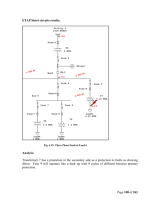
This chapter introduces the project, which is to create an advanced user guide for the ETAP software to analyze power system protection designs. The guide will explain how to create a one-line diagram, configure protection equipment, perform fault and short circuit analysis. The objectives are to help engineers learn and apply ETAP, while the constraints include completing all tasks by the deadline and within budget.
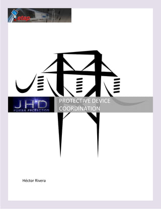


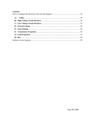


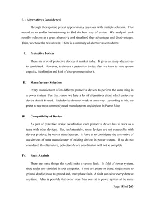
![Cero sequence impedance to determine a short circuit current at the bus 2:
Fig. 4.35: Zero Sequence Impedance Diagram
at Bus 2 Using Generators.
Z 0TH = Z G1 // Z G 2 + Z L 3 + Z L 5 = (0.816*10−3 + 1.734 *10 −3 ) pu = 2.55*10 −3 pu
Doing a short circuit at the bus 2:
1∠0
I0 = = 67.29 pu
[ 2(0.006155) + 0.00255] pu
I SCH = (67.29 pu )(3) = 201.88 pu
Changing the per unit current to real current:
I SCH = (201.88 pu )(694.68 A) = 140, 244.95 A
Page 123 of 263](https://image.slidesharecdn.com/protectivedevicecoordination-12602548898887-phpapp01/85/Protective-Device-Coordination-123-320.jpg)
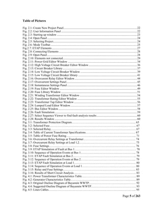
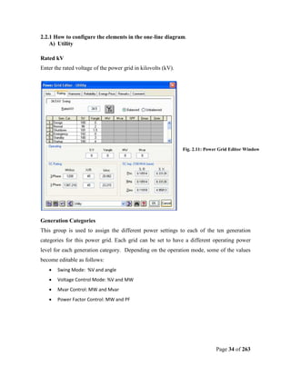
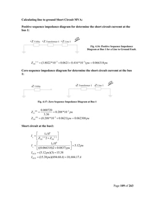
![Positive sequence impedance to determine a short circuit current at the load 1:
Fig. 4.36: Positive Sequence Impedance
Diagram at Load 1 Using Generators for a
Line to Ground Fault.
ZTH + = (6.155*10−3 + 0.078*10−3 + 0.1) pu = 0.1062 pu
Cero sequence impedance to determine a short circuit current at the load 1:
Fig. 4.37: Zero Sequence Impedance Diagram
at Load 1 Using Generators.
Doing a short circuit at the load 1:
Z 0TH = ZT 2 = 0.1 pu
The short circuit current:
1∠0
I0 = = 3.2 pu
[ 2(0.1062) + 0.1] pu
I SCH = (3.2 pu )(3) = 9.6 pu
Converting the per unit current to real current:
I SCH = (9.6 pu )(6020.56 A) = 57,815.87 A
Page 124 of 263](https://image.slidesharecdn.com/protectivedevicecoordination-12602548898887-phpapp01/85/Protective-Device-Coordination-124-320.jpg)
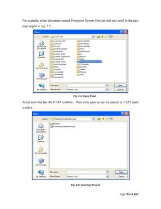
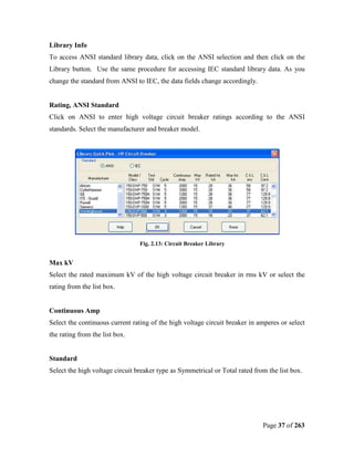
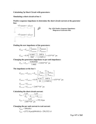
![Positive sequence impedance to determine a short circuit current at the load 5:
Fig. 4.38: Positive Sequence Impedance
Diagram at Load 5 Using Generators for a
Line to Ground Fault.
Z + TH = Z G1+ LG1 // Z G 2+ LG 2 + Z L 4 + Z L 9 + Z T 7 = (0.816 *10−3 + 1.272 *10−3 + 0.833) pu = 0.835 pu
Cero sequence impedance to determine a short circuit current at the load 5:
Fig. 4.39: Zero Sequence Impedance Diagram
at Load 5 Using Generators.
Z 0TH = ZT 7 = 0.833 pu
Doing a short circuit at the secondary side of the transformer 7:
1∠0
I0 = = 0.39 pu
[ 2(0.835) + 0.833] pu
I SCH = (0.39 pu )(3) = 1.19 pu
Changing the per unit current to real current:
I SCH = (1.19 pu )(6020.56 A) = 7,164.46 A
Page 125 of 263](https://image.slidesharecdn.com/protectivedevicecoordination-12602548898887-phpapp01/85/Protective-Device-Coordination-125-320.jpg)


![5.5 Bibliography
• Power System Protection, [Online]. Available:
http://en.wikipedia.org/wiki/Protection_and_monitoring_of_the_electrical_energy_t
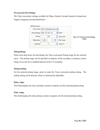
ransmission_networks
• Electrical Engineering History, [Online]. Available:
http://www.history.com/encyclopedia.do?articleId=208367
• Electricity, [Online]. Available:
http://www.eia.doe.gov/kids/history/timelines/electricity.html
• Short Circuit Analysis, [Online]. Available: http://www.answers.com/topic/short-
circuit?cat=technology
• General Electric: (www.ge.com/products_services/electrical_distribution.html).
• ABB: (http://www.abb.com/ProductGuide/Alphabetical.aspx)
• Cutler Hammer:
(http://www.eaton.com/EatonCom/Markets/Electrical/Products/SwitchingDevicesan
dDisconnects/EnclosedCircuitBreakers/index.htm)
• Siemens: (http://w1.siemens.com/en/us/entry.html)
• Square D:
(http://www.squared.com/us/squared/corporate_info.nsf/unid/ECA90110AB7098C
A85256A3A007091D7/$file/productsa2zFrameset.htm)
• ETAP Program, [Online] Available: www.etap.com
• International Electric Power Encyclopedia, 1998 Per Wel, Publishing Company,
Tulas, UK.
• International Electric Power Encyclopedia, 1999 Per Wel, Publishing Company,
Tulas, UK.
• Zaberszky, John; Rittenhouse, Joseph W.; Electric Power Transmission, The Ronald
Press Company, 1954.
• T. Davies C., Protection of Industrial Power Systems; Pergamon Press, 1984.
• Duncan Glober, J.; Sarma Mulukutla; Power System Analysis and Design; PWS-
KENT Publishing Company, Boston.
• Anderson, P.M.; Power System Protection; McGraw Hill, 1998.
Page 199 of 263](https://image.slidesharecdn.com/protectivedevicecoordination-12602548898887-phpapp01/85/Protective-Device-Coordination-199-320.jpg)


![References
• [Online]. Available:
http://en.wikipedia.org/wiki/Protection_and_monitoring_of_the_electrical_energy_t
ransmission_networks
• [Online]. Available: http://www.history.com/encyclopedia.do?articleId=208367
• [Online]. Available:
http://www.eia.doe.gov/kids/history/timelines/electricity.html
• [Online]. Available: http://www.answers.com/topic/short-circuit?cat=technology
• General Electric: (www.ge.com/products_services/electrical_distribution.html).
• ABB: (http://www.abb.com/ProductGuide/Alphabetical.aspx)
• Cutler Hammer:
(http://www.eaton.com/EatonCom/Markets/Electrical/Products/SwitchingDevicesan
dDisconnects/EnclosedCircuitBreakers/index.htm)
• Siemens: (http://w1.siemens.com/en/us/entry.html)
• Square D:
(http://www.squared.com/us/squared/corporate_info.nsf/unid/ECA90110AB7098C
A85256A3A007091D7/$file/productsa2zFrameset.htm)
Page 221 of 263](https://image.slidesharecdn.com/protectivedevicecoordination-12602548898887-phpapp01/85/Protective-Device-Coordination-221-320.jpg)