Download as PPSX, PPTX


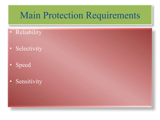
![• Rated Voltage 145 KV
• Rated Current 1250 A Frequency 50 Hz
• Breaking Capacity 40 KA
• Making Capacity 100 KVP
• Short Time Rating 40 KA for 3 sec
• Operating sequence
O-0.3 sec - CO- 3 MIN- CO
• Trip and Closing Coil Voltage 110V DC
• Motor Supply 240 V
11
These are used to operate on the fault on line or X-mer depending upon where it is
connected. This isolates the faulty line or equipments from the live portion of the sub
station by opening automatically through protective relays; control cables etc. in
definite time.
Testing for SF6:-
Applied Volt 5KV DC
•IR Value
> 20 GΩ CB ON
[R(Y+B+E),Y(R+B+E),B(R+Y+E)]
> 50 GΩ CB OFF
[R-R’,Y-Y’,B-B’]
•Applied current 100 A DC
Contact Resistance test: R-ø ,Y-ø B-ø < 34 μΩ
•SF6 Gas pressure setting 5.4 bar.
•Breaker , Closing Time 72 ms
Opening Time -29 ms Each Phase](https://image.slidesharecdn.com/switchyardmanoj-130911153440-phpapp01/85/Switch-yard-Protection-11-320.jpg)

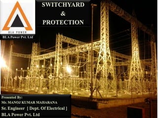
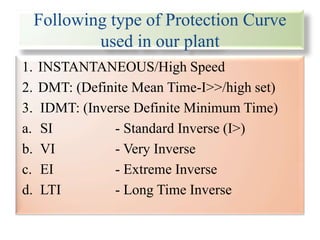
![Common Testing's Required for CT & PT:-
•IR Test :
Applied Volt 5KV DC
> 10 GΩ [Prim – Earth, Prim – Core]
Applied Volt 1KV DC
> 500 MΩ [Core-Earth]
•Winding Resistance Test:
< 5-6 Ω [Ex: R-ø ,1s1-1s2,1s1-1s3]
•Ratio Test :
[Prim current 400-800]/ [Sec. current 1-1A]
[Ex: R-ø ,1s1-1s2,2s1-2s2]
•Polarity Test :
[Ex: R-ø ,1s1-1s2,2s1-2s2]
•Knee voltage Test:
[Only For Protection Class CT ]
is significance of saturation level of a current
transformer core mainly used for protection
purposes. The sinusoidal voltage of rated
frequency is applied to the secondary
terminals of CT, with other winding being
open circuited which increased by10%, cause
the exiting current to increase by 50%. NEXT
Press](https://image.slidesharecdn.com/switchyardmanoj-130911153440-phpapp01/85/Switch-yard-Protection-13-320.jpg)

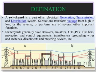
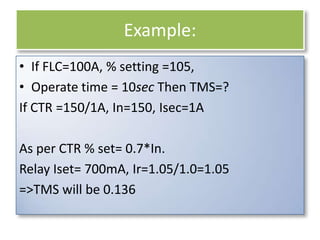
![17
•Bus: is a line in which the incoming feeder
come into & get into the instruments for
further step up or step down.
•Double line in the bus so that if any fault
occurs in one the other can still have the
current and the supply will not stop.
•Two lines are separated by a little distance by
a conductor [spacer] having a connector
between them .
Spacer
Clamp
Tension
Suspension](https://image.slidesharecdn.com/switchyardmanoj-130911153440-phpapp01/85/Switch-yard-Protection-17-320.jpg)


![Special Thanks
• for Guidance
Mr. U.P. Sharma
Sr. Manager [ Dept. Of Electrical ]
• for Co-ordination
Mr. Nilesh Malviya
Mr. Dhanajya Ray
Engineer [ Dept. Of Electrical ]
52](https://image.slidesharecdn.com/switchyardmanoj-130911153440-phpapp01/85/Switch-yard-Protection-52-320.jpg)


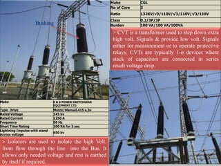
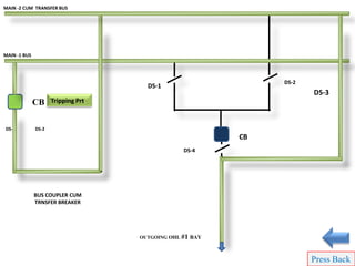
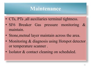
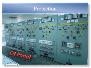
This document provides information about the construction, components, testing, operation, protection and maintenance of a 132kV switchyard. It includes details about the bus bars, circuit breakers, current transformers, potential transformers, wave traps, isolators, control and protection schemes. The key components of the switchyard are described along with their ratings and testing procedures. The operational modes and protection philosophy are also summarized.