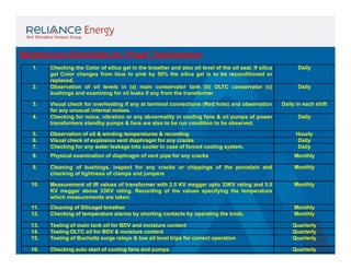
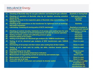
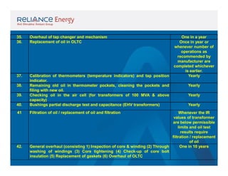
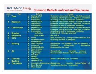
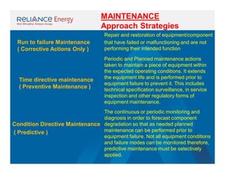
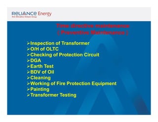
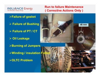
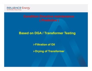
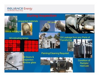
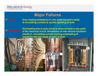
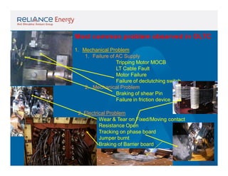
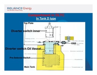
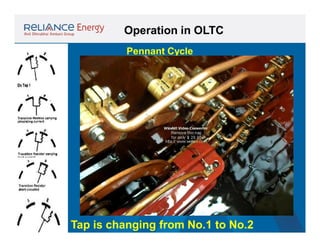
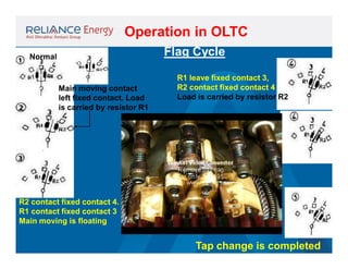
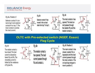
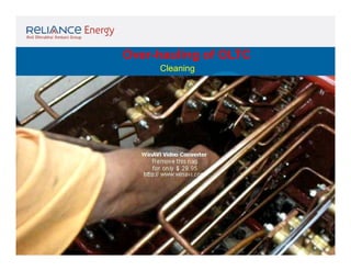
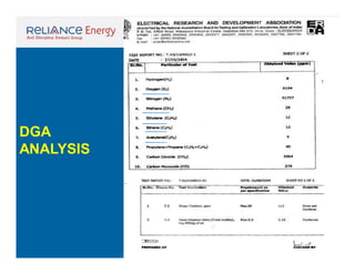
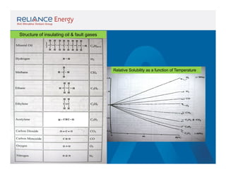
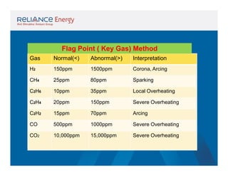
This document discusses maintenance schedules and strategies for electrical substation equipment like power transformers and distribution transformers. It provides daily, monthly, quarterly, half-yearly, and annual maintenance tasks for checking equipment operation and performance. Key tasks include checking oil levels, insulation resistance, dissolved gases in oil, and cleaning/replacing oil filters. The document also summarizes common equipment defects like leaks, loose connections, and winding issues; and stresses on equipment from electrical, thermal, mechanical, and environmental factors that cause deterioration over time.
Tan delta is the insulation power factor & is equal to the ratio of power dissipated in the insulation in watts to the product of effective voltage & current in volt ampere when tested under sinusoidal voltage.
How is power transformer protected??? This provides a basic understanding of power transformer. Furthermore, the protective relay application on power transformer is included.
Practical handbook-for-relay-protection-engineersSARAVANAN A
Â
The âHand Bookâ covers the Code of Practice in Protection Circuitry including standard lead and device numbers, mode of connections at terminal strips, colour codes in multicore cables, Dos and Donts in execution. Also, principles of various protective relays and schemes including special protection schemes like differential,
restricted, directional and distance relays are explained with sketches. The norms of protection of generators, transformers, lines & Capacitor Banks are also given.
Testing and Condition Monitoring of Substation EquipmentsSumeet Ratnawat
Â
Testing and condition monitoring of substation equipments,Transformer specifications,Monitoring of Transformer,On-load Tap changer,Overhauling,Tan delta and capacitance,Thermal imaging,Sweep frequency response analysis,Oil analysis of Switchgear elements containing oil,tests on insulating oil,Breaker monitoring,Condition monitoring of CT,Condition monitoring of CVT,Surge Arresters,Condition monitoring of relays.
Unit I: Introduction to Protection System:
Introduction to protection system and its elements, functions of protective relaying, protective zones, primary and backup protection, desirable qualities of protective relaying, basic terminology.
Relays:
Electromagnetic, attracted and induction type relays, thermal relay, gas actuated relay, design considerations of electromagnetic relay.
Unit-II: Relay Application and Characteristics:
Amplitude and phase comparators, over current relays, directional relays, distance relays, differential relay.
Static Relays: Comparison with electromagnetic relay, classification and their description, over current relays, directional relay, distance relays, differential relay.
Unit-III Protection of Transmission Line:
Over current protection, distance protection, pilot wire protection, carrier current protection, protection of bus, auto re-closing,
Unit-IV: Circuit Breaking:
Properties of arc, arc extinction theories, re-striking voltage transient, current chopping, resistance switching, capacitive current interruption, short line interruption, circuit breaker ratings.
Testing Of Circuit Breaker: Classification, testing station and equipments, testing procedure, direct and indirect testing.
Unit-V Apparatus Protection:
Protection of Transformer, generator and motor.
Circuit Breaker: Operating modes, selection of circuit breakers, constructional features and operation of Bulk Oil, Minimum Oil, Air Blast, SF6, Vacuum and d. c. circuit breakers.
This Presentation is about l.v switch gear design, presented during the graduation project final discussion 15/7/2018.
It presented a good summary of switch gear components and types and practicing on AL.HAMOOL W.T.P M.D.B design using SIEMENS SIVACON S8
On Load Tap Changer (OLTC) is used in "High Power Transformers" to control output voltage, when electric load on transformers get increase the output voltage get decrease due to internal voltage drop inside winding, change in tap is required to maintain output voltage. OLTC is a device which perform tap changing in High Power Transformers during On Load conditions and is powered by a motor.
Mr. Veerabrahmam from PRDC has spoken about the transformers failures and few of the case studies. Few failures and reasons for failures are also discussed.
Test done on Power transformers.
Insulation Resistance test, Winding Resistance test, Ratio Measurements, Magnetic balance test, Tan delta test, DIssolved gas analysis for transformer, Sweep frequency response analysis.
A switchgear or electrical switchgear is a generic term which includes all the switching devices associated with mainly power system protection. It also includes all devices associated with control, metering and regulating of electrical power system. Assembly of such devices in a logical manner forms a switchgear. This is the very basic definition of switchgear.
âTo get more with details
https://www.youtube.com/channel/UC2SvKI7eepP241VLoui1D5A
In-Country Training
On
Operation, Maintenance, Protection & Control of 33/11 kV Substation
Project Name: Design, Supply, Installation, Testing & Commissioning of 33/11 kV sub-stations with source end feeder bays.
Â
Contract No: BREB/UREDS/W-01A-001/02/2016-2017
BREB/UREDS/W-01A-002/03/2016-2017
BREB/UREDS/W-01A-004/04/2016-2017
Installation Operation & Maintenance of 33kV & 11kV SwitchgearSheikh Nazmul Islam
Â
In-Country Training On Operation, Maintenance, Protection & Control of 33/11 kV Substation Project Name: Design, Supply, Installation, Testing & Commissioning of 33/11 kV sub-stations with source end feeder bays. Contract No: BREB/UREDS/W-01A-001/02/2016-2017 BREB/UREDS/W-01A-002/03/2016-2017 BREB/UREDS/W-01A-004/04/2016-2017
LA HUG - Video Testimonials with Chynna Morgan - June 2024Lital Barkan
Â
Have you ever heard that user-generated content or video testimonials can take your brand to the next level? We will explore how you can effectively use video testimonials to leverage and boost your sales, content strategy, and increase your CRM data.đ¤Ż
We will dig deeper into:
1. How to capture video testimonials that convert from your audience đĽ
2. How to leverage your testimonials to boost your sales đ˛
3. How you can capture more CRM data to understand your audience better through video testimonials. đ
Premium MEAN Stack Development Solutions for Modern BusinessesSynapseIndia
Â
Stay ahead of the curve with our premium MEAN Stack Development Solutions. Our expert developers utilize MongoDB, Express.js, AngularJS, and Node.js to create modern and responsive web applications. Trust us for cutting-edge solutions that drive your business growth and success.
Know more: https://www.synapseindia.com/technology/mean-stack-development-company.html
Enterprise Excellence is Inclusive Excellence.pdfKaiNexus
Â
Enterprise excellence and inclusive excellence are closely linked, and real-world challenges have shown that both are essential to the success of any organization. To achieve enterprise excellence, organizations must focus on improving their operations and processes while creating an inclusive environment that engages everyone. In this interactive session, the facilitator will highlight commonly established business practices and how they limit our ability to engage everyone every day. More importantly, though, participants will likely gain increased awareness of what we can do differently to maximize enterprise excellence through deliberate inclusion.
What is Enterprise Excellence?
Enterprise Excellence is a holistic approach that's aimed at achieving world-class performance across all aspects of the organization.
What might I learn?
A way to engage all in creating Inclusive Excellence. Lessons from the US military and their parallels to the story of Harry Potter. How belt systems and CI teams can destroy inclusive practices. How leadership language invites people to the party. There are three things leaders can do to engage everyone every day: maximizing psychological safety to create environments where folks learn, contribute, and challenge the status quo.
Who might benefit? Anyone and everyone leading folks from the shop floor to top floor.
Dr. William Harvey is a seasoned Operations Leader with extensive experience in chemical processing, manufacturing, and operations management. At Michelman, he currently oversees multiple sites, leading teams in strategic planning and coaching/practicing continuous improvement. William is set to start his eighth year of teaching at the University of Cincinnati where he teaches marketing, finance, and management. William holds various certifications in change management, quality, leadership, operational excellence, team building, and DiSC, among others.
Attending a job Interview for B1 and B2 Englsih learnersErika906060
Â
It is a sample of an interview for a business english class for pre-intermediate and intermediate english students with emphasis on the speking ability.
3.0 Project 2_ Developing My Brand Identity Kit.pptxtanyjahb
Â
A personal brand exploration presentation summarizes an individual's unique qualities and goals, covering strengths, values, passions, and target audience. It helps individuals understand what makes them stand out, their desired image, and how they aim to achieve it.
Tata Group Dials Taiwan for Its Chipmaking Ambition in Gujaratâs DholeraAvirahi City Dholera
Â
The Tata Group, a titan of Indian industry, is making waves with its advanced talks with Taiwanese chipmakers Powerchip Semiconductor Manufacturing Corporation (PSMC) and UMC Group. The goal? Establishing a cutting-edge semiconductor fabrication unit (fab) in Dholera, Gujarat. This isnât just any project; itâs a potential game changer for Indiaâs chipmaking aspirations and a boon for investors seeking promising residential projects in dholera sir.
Visit : https://www.avirahi.com/blog/tata-group-dials-taiwan-for-its-chipmaking-ambition-in-gujarats-dholera/
Skye Residences | Extended Stay Residences Near Toronto Airportmarketingjdass
Â
Experience unparalleled EXTENDED STAY and comfort at Skye Residences located just minutes from Toronto Airport. Discover sophisticated accommodations tailored for discerning travelers.
Website Link :
https://skyeresidences.com/
https://skyeresidences.com/about-us/
https://skyeresidences.com/gallery/
https://skyeresidences.com/rooms/
https://skyeresidences.com/near-by-attractions/
https://skyeresidences.com/commute/
https://skyeresidences.com/contact/
https://skyeresidences.com/queen-suite-with-sofa-bed/
https://skyeresidences.com/queen-suite-with-sofa-bed-and-balcony/
https://skyeresidences.com/queen-suite-with-sofa-bed-accessible/
https://skyeresidences.com/2-bedroom-deluxe-queen-suite-with-sofa-bed/
https://skyeresidences.com/2-bedroom-deluxe-king-queen-suite-with-sofa-bed/
https://skyeresidences.com/2-bedroom-deluxe-queen-suite-with-sofa-bed-accessible/
#Skye Residences Etobicoke, #Skye Residences Near Toronto Airport, #Skye Residences Toronto, #Skye Hotel Toronto, #Skye Hotel Near Toronto Airport, #Hotel Near Toronto Airport, #Near Toronto Airport Accommodation, #Suites Near Toronto Airport, #Etobicoke Suites Near Airport, #Hotel Near Toronto Pearson International Airport, #Toronto Airport Suite Rentals, #Pearson Airport Hotel Suites
Business Valuation Principles for EntrepreneursBen Wann
Â
This insightful presentation is designed to equip entrepreneurs with the essential knowledge and tools needed to accurately value their businesses. Understanding business valuation is crucial for making informed decisions, whether you're seeking investment, planning to sell, or simply want to gauge your company's worth.
Memorandum Of Association Constitution of Company.pptseri bangash
Â
www.seribangash.com
A Memorandum of Association (MOA) is a legal document that outlines the fundamental principles and objectives upon which a company operates. It serves as the company's charter or constitution and defines the scope of its activities. Here's a detailed note on the MOA:
Contents of Memorandum of Association:
Name Clause: This clause states the name of the company, which should end with words like "Limited" or "Ltd." for a public limited company and "Private Limited" or "Pvt. Ltd." for a private limited company.
https://seribangash.com/article-of-association-is-legal-doc-of-company/
Registered Office Clause: It specifies the location where the company's registered office is situated. This office is where all official communications and notices are sent.
Objective Clause: This clause delineates the main objectives for which the company is formed. It's important to define these objectives clearly, as the company cannot undertake activities beyond those mentioned in this clause.
www.seribangash.com
Liability Clause: It outlines the extent of liability of the company's members. In the case of companies limited by shares, the liability of members is limited to the amount unpaid on their shares. For companies limited by guarantee, members' liability is limited to the amount they undertake to contribute if the company is wound up.
https://seribangash.com/promotors-is-person-conceived-formation-company/
Capital Clause: This clause specifies the authorized capital of the company, i.e., the maximum amount of share capital the company is authorized to issue. It also mentions the division of this capital into shares and their respective nominal value.
Association Clause: It simply states that the subscribers wish to form a company and agree to become members of it, in accordance with the terms of the MOA.
Importance of Memorandum of Association:
Legal Requirement: The MOA is a legal requirement for the formation of a company. It must be filed with the Registrar of Companies during the incorporation process.
Constitutional Document: It serves as the company's constitutional document, defining its scope, powers, and limitations.
Protection of Members: It protects the interests of the company's members by clearly defining the objectives and limiting their liability.
External Communication: It provides clarity to external parties, such as investors, creditors, and regulatory authorities, regarding the company's objectives and powers.
https://seribangash.com/difference-public-and-private-company-law/
Binding Authority: The company and its members are bound by the provisions of the MOA. Any action taken beyond its scope may be considered ultra vires (beyond the powers) of the company and therefore void.
Amendment of MOA:
While the MOA lays down the company's fundamental principles, it is not entirely immutable. It can be amended, but only under specific circumstances and in compliance with legal procedures. Amendments typically require shareholder
Affordable Stationery Printing Services in Jaipur | Navpack n PrintNavpack & Print
Â
Looking for professional printing services in Jaipur? Navpack n Print offers high-quality and affordable stationery printing for all your business needs. Stand out with custom stationery designs and fast turnaround times. Contact us today for a quote!
Unveiling the Secrets How Does Generative AI Work.pdfSam H
Â
At its core, generative artificial intelligence relies on the concept of generative models, which serve as engines that churn out entirely new data resembling their training data. It is like a sculptor who has studied so many forms found in nature and then uses this knowledge to create sculptures from his imagination that have never been seen before anywhere else. If taken to cyberspace, gans work almost the same way.
2. Maintenance may be defined as the upkeep
of the sub stationâs electrical equipments in
proper working condition and efficient to
derive the following :
#
#
#
#
#
#
Reliable and efficient operation
Optimum utilisation
Availability
Reduced down time
Detection of premature faults
Minimizing revenue loss etc.
To meet the above requirement, the equipment has
to be checked, attended, to trouble-shot and
operated under specified conditions.
3. The need for maintenance
During the operational life of the electrical equipment,
ageing occurs due to various stresses which is incident
on the equipment both under normal and fault conditions
and result in deterioration of physical and chemical
properties of components making up the electrical
equipment.
The expected performance can not be obtained from the
equipment once it is aged.
4. The electrical equipment in service are subject to
the following stresses :
⢠Electrical stresses
⢠Thermal stresses
⢠Mechanical stresses
⢠Environmental stresses
⢠Combined stresses
5. Electrical Stress:
The Insulation of electrical equipment experience the
following voltages :
⢠Continuous normal power frequency rated voltage
⢠Temporary power frequency over voltages due to voltage
regulation, Ferranti effect, and long duration power
frequency over voltages.
⢠Lightning Impulse Voltage Waves (Surges)
⢠Switching Impulse Waves (Surges)
6. Thermal Stress
Elevated temperatures may be reached during
operation due to dielectric losses, increased I2R loss
or by heat absorption from surroundings.
Temperature may increase abnormally due to
sustained short circuit current.
The cooling system failure in power transformers
also stress the windings thermally.
7. Mechanical Stress
There may be permanent mechanical stress due
to improper installation
Circuit breakers may experience vibration stress
during normal closing/opening and during making /
breaking under fault
The bus bar vibration in rigid bus bar stresses the
bus bar support mechanically
8. Environmental stress
Environmental factors include pollution, Radiation,
Humidity, dust particles, moisture etc,.
Proximity to chemical industry, sea coast and
intentional damage caused by humans contribute to
ageing and deterioration
Combined stress
In most of the electrical equipment, normally
some of the stress factors as above will be present
9.
10. Maintenance Schedules for Power Transformers
1.
2.
3.
4.
Checking the Color of silica gel in the breather and also oil level of the oil seal. If silica
gel Color changes from blue to pink by 50% the silica gel is to be reconditioned or
replaced.
Observation of oil levels in (a) main conservator tank (b) OLTC conservator (c)
bushings and examining for oil leaks if any from the transformer
Daily
Visual check for overheating if any at terminal connections (Red hots) and observation
for any unusual internal noises.
Checking for noice, vibration or any abnormality in cooling fans & oil pumps of power
transformers standby pumps & fans are also to be run condition to be observed.
Daily in each shift
Daily
Daily
5.
6.
7.
Observation of oil & winding temperatures & recording
Visual check of explosion vent diaphragm for any cracks
Checking for any water leakage into cooler in case of forced cooling system.
Hourly
Daily
Daily
8.
Physical examination of diaphragm of vent pipe for any cracks
Monthly
9.
Cleaning of bushings, inspect for any cracks or chippings of the porcelain and
checking of tightness of clamps and jumpers
Monthly
10.
Measurement of IR values of transformer with 2.5 KV megger upto 33KV rating and 5.0
KV megger above 33KV rating. Recording of the values specifying the temperature
which measurements are taken.
Monthly
11.
12.
Cleaning of Silicagel breather
Checking of temperature alarms by shorting contacts by operating the knob.
Monthly
Monthly
13.
14.
15.
Testing of main tank oil for BDV and moisture content
Testing OLTC oil for BDV & moisture content
Testing of Bucholtz surge relays & low oil level trips for correct operation
Quarterly
Quarterly
Quarterly
16.
Checking auto start of cooling fans and pumps
Quarterly
11. 17.
Checking of Bucholtz relay for any gas collection and testing the gas collected
18.
Checking of operation of Bucholtz relay by air injection ensuring actuation
alaram & trip
Noting the oil level in the inspection glass of Bucholtz relay and arresting of oil
leakages if any.
Checking of all connections on the transformer for tightness such as bushings,
tank earth connection
Lubricating / Greasing all moving parts of OLTC mechanism
Half yearly or during
shutdown
Monthly
Testing of oil for dissolved gas analysis of EHV transformers upto 100KVA
capacity
Overhauling of oil pumps and their motors also cooling fans & their motors.
Once in a year
Once in a year
29.
30.
31.
Testing of oil in main tank for acidity, tan delta, interface tension specific
resisitivity
Bushing testing for tan delta
Calibration of oil & winding temperature indicators
Measurement of magnetizing current at normal tap and extreme taps
32.
33.
34.
Measurement of DC winding resistance
Turns ratio test at all taps
Inspection of OLTC mechanism and contacts its diverter switch
19.
20.
21.
22.
23.
24.
25.
26
27.
28.
Quarterly or during fault
Quarterly
Quarterly or as given in
the manufacturers manual
Checking of control circuitry, interlocks of oil pumps and cooling fans for auto
Half yearly or during
start and stop operation at correct temperatures and also for manual operation
shutdown
Testing of motors, pumps and calibrating pressure gauge
Half yearly
Pressure testing of oil coolers
Half yearly
Testing of oil samples for dissolved gas analysis (for 100MVA transformers)
Half yearly
Once in a year
Once in a year
Repeats
One in a year
Once in a year
Once in a year
Once in a year or number
of operation as
recommended by
manufacturers are
completed whichever is
12. 35.
36.
Overhaul of tap changer and mechanism
Replacement of oil in OLTC
37.
40.
Calibration of thermometers (temperature indicators) and tap position
indicator.
Remaining old oil in thermometer pockets, cleaning the pockets and
filing with new oil.
Checking oil in the air cell (for transformers of 100 MVA & above
capacity)
Bushings partial discharge test and capacitance (EHV transformers)
41
Filtration of oil / replacement of oil and filtration
38.
39.
42.
One in a year
Once in year or
whenever number of
operations as
recommended by
manufacturer are
completed whichever
is earlier.
Yearly
Yearly
Yearly
Yearly
Whenever the IR
values of transformer
are below permissible
limits and oil test
results require
filtration / replacement
of oil
One in 10 years
General overhaul (consisting 1) Inspection of core & winding (2) Through
washing of windings (3) Core tightening (4) Check-up of core bolt
insulation (5) Replacement of gaskets (6) Overhaul of OLTC
13. Maintenance Schedule of Distribution Transformers
1.
Cleaning of bushings and external surface of tank cooling pipes
Monthly
2.
Checking of oil levels in the conservator and gauge glass
Monthly
3.
Checking of silicased in the breather and replacement is necessary
Monthly
4.
Checking of oil level in the oil seal of breather & top up if necessary
Monthly
5.
Checking of HG fuse & LT fuse and renew if necessary (correct
guage shall maintained)
Checking of vent pipe diaphragm
Checking of terminal loose connections is any and tightening the
same
Checking for any oil leaks & rectification (including replacement of
oil seals if required)
Taking long tester reading during peak load hours and remedial
action
Noting down neutral currents and load balancing in all the three
phase
Measurement of IR Values
Testing of oil for BDV, activity
Checking of lightening arrestors and replacement is required once
before monsoon)
Measurement of earth resistance checking of earthing system and
rectification if required.
Overhaul of transformer
Monthly
6.
7.
8.
9.
10.
11.
12.
13.
14.
15.
Monthly
Monthly
Monthly
Quarterly
Quarterly
Half yearly
Half yearly
Half yearly
Half yearly
Once in 5 years
14. Common Defects noticed and the cause
Sl.No
Part
1.
Tank
2.
Radiators
3.
Conservator
4.
5.
6.
Breather
Explosion
Core
7.
Winding
8.
Oil
9.
Terminal
Bushing
Tap Switch
10
a.
b.
c.
a.
b.
c.
d.
a.
b.
c.
d.
a.
b.
Defects
Leakage of oil
Deformation
Overheating
Leakage of Oil
Deformation
Overheating
Leakage of Oil
Deformation
Overheating
Ineffective
Glass broken
Loose
Increased Losses
Excess Noise
Short Circuited
Loosening
Insulation Brittle
Open circuited
Discoloration
High Acidity
Low BDV
Sludge
Breakage
Leakage of Oil
a.
b.
c.
Inoperative Broken lever Maloperation â Insulation failureâFailure
Burnt Contact
operation mechanism â overheating
Short Circuit
a.
b.
c.
a.
b.
c.
a.
b.
c.
Causes
Corrosion / mechanical damage â Gaskets worn out
excessive internal pressure â Improper circulation
of cooling oil and / or inadequate ventilation.
Corrosion / mechanical damage â Gaskets worn out
excessive internal pressure â Improper circulation
of cooling oil and / or inadequate ventilation.
Corrosion / mechanical damage â Gaskets worn out
excessive internal pressure â Improper circulation
of cooling oil and / or inadequate ventilation.
Inlet choked â Silica gel saturated
Mechanical
Bolts loosening up â change in characteristics due
to heating vibration of stampings
Overloading â Air bubbles â loss of insulation â
shrinkage
displacement
Overheating
decomposition burn out.
Contamination
â
Increased
moisture
Decomposition chemical action with other parts.
â
Strain â Gasket Worn out â Loose fit.
of
15. MAINTENANCE
Approach Strategies
Run to failure Maintenance
( Corrective Actions Only )
Time directive maintenance
( Preventive Maintenance )
Repair and restoration of equipment/component
that have failed or malfunctioning and are not
performing their intended function
Periodic and Planned maintenance actions
taken to maintain a piece of equipment within
the expected operating conditions. It extends
the equipment life and is performed prior to
equipment failure to prevent it. This includes
technical specification surveillance, in service
inspection and other regulatory forms of
equipment maintenance.
The continuous or periodic monitoring and
diagnosis in order to forecast component
Condition Directive Maintenance degradation so that as needed planned
maintenance can be performed prior to
( Predictive )
equipment failure. Not all equipment conditions
and failure modes can be monitored therefore,
predictive maintenance must be selectively
applied.
16. Time directive maintenance
( Preventive Maintenance )
ďInspection of Transformer
ďO/H of OLTC
ďChecking of Protection Circuit
ďDGA
ďEarth Test
ďBDV of Oil
ďCleaning
ďWorking of Fire Protection Equipment
ďPainting
ďTransformer Testing
17. Run to failure Maintenance
( Corrective Actions Only )
ďFailure of gasket
ď Failure of Bushing
ď Failure of PT / CT
ď Oil Leakage
ďBurning of Jumpers
ďWinding / insulation Failed
ďOLTC Problem
19. During Inspection
Unwanted materials
Oil Level
Silica Jell degraded
All indicating lamps
Oil Leakage from any Parts of
Transformer
Painting/Cleaning Required
All Doors &
inspection
window glass
Condition of
Radiator
Hot/Cold
20. Major Failures
ď Core
Over heating breakdown in core plate insulation leads
to circulating currents & usually sparking at fault.
ď Winding
Overheating due to poor joints is common fault in any parts
of the electrical circuit. Breakdown of inter-strand insulation
results in circulating current causing overheating of
insulation and hot spots at point of fault
Poor joints
21. Most common problem observed in OLTC
OLTC
1. Mechanical Problem
1. Failure of AC Supply
Tripping Motor MOCB
LT Cable Fault
Motor Failure
Failure of declutching switch
2. Mechanical Problem
Braking of shear Pin
Failure in friction device
2. Electrical Problem
Wear & Tear on Fixed/Moving contact
Resistance Open
Tracking on phase board
Jumper burnt
Braking of Barrier board
22. The OLTC provides uninterrupted
voltage regulation of transformers
under load.
The voltage is regulated by changing
the voltage ratio. This is done in steps.
The transformer is equipped with a tap
winding whose tapping are connected
with the tap selector of the OLTC
23. Changing Voltage Ratio
a. Linear Voltage Regulation
c. Coarse & fine Voltage regulation
Step Voltage
is 200 Volt/tap
b. Reversing Voltage Regulation
26. Reversing Voltage Regulation
We have different makes OLTC
Flange Mounted OLTC
Crompton AT
In Tank
(A) With Pre-Selector Switch
(B) Without Pre-Selector Switch
Easun
NGEF
Diverter switch
BHEL
(A)
(B)
Pre-Selector Switch
27. Compartment in OLTC
Flange Mounted OLTC
Driving Mechanism
High Speed Selector switch
Selector switch is capable of making &
Breaking load in addition to selecting tap
A chamber houses the motor
and driving mechanism
28. Compartment in OLTC
Top Plate
In Tank V type
Selector Switch
Inside the
Main Tank
Transmission Shaft
Driving Mechanism
29. Compartment in OLTC
In Tank D type
Top Plate
Diverter switch inner
OSR
Diverter switch Oil Vessel
Pre-Selector Switch
Main Tank
31. Operation in OLTC
Flag Cycle
Normal
Main moving contact
left fixed contact. Load
is carried by resistor R1
R1 leave fixed contact 3,
R2 contact fixed contact 4
Load is carried by resistor R2
R2 contact fixed contact 4.
R1 contact fixed contact 3
Main moving is floating
Tap change is completed
36. AVR mounted on RTCC
Automatic Voltage Regulating Relay (AVR):
AVR is used to maintain secondary voltage (11KV) of power
transformer by operating primary side (22/33KV) OLTC Tap.
Input to AVR is secondary side of 11000/110V Potential
transformer directly connected on secondary side of Power
Transformer (Circuit PT or Transformer PT).
EMCO, NMC, Pradeep and accord make AVRs are in service.
Typical settings of AVRs â
Auxiliary supply = 110V AC
Nominal Voltage = 110V AC (From 11000/110V PT)
Raise Operation : V <108V
Lower Operation : V >112V
Time Delay = 120 Sec.
37. Directional Sequence Switch (DSS):
DSS is cam operated multiple contact switch used to maintain OLTC motor supply to
during operation and cut-off after completion of OLTC operation.
Switron, Shirke Electricals, Recom make
DSS are in service.
Typical DSS contacts and their application
is as follows.
38. Electrical Interlocks And Protection:
Directional Raise Limit switch â Blocks
electrical raise operation when tap at
maximum position (Tap15 or 16).
Directional Lower Limit switch â Blocks
electrical lower operation when tap at
minimum position (Tap1).
Motor Protection Relay
(MPR) â Driving motor is
protected for overload by
MPR which isolates it
under fault condition.
Hand Interlock Switch (HIS) â
HIS isolates electrical supply
during manual crank handle is
in. Ensures safety to operating
personal.
OLTC Timer Scheme â Timer scheme will
operate if motor supply is continuous for more
than set time (Set time=2*time for one operation)
and avoids high/lower voltages during DSS and
contactor mal-operation .
39. Protection for OLTC
⢠OSR
⢠Motor Stuck up Alarm
⢠Motor Supply Failed Alarm
OLTC PRV
On RTCC
42. CONDITION MONITORING OF
TRANSFORMER OIL
Parameters for condition monitoring of oil service
Two ways are available to an operating engineer
1.To make periodic oil tests to establish trends and classify
them.
2.To conduct dissolved gas analysis to assess the internal
condition of transformers
43. PARAMETERS TO BE CHECKED ARE:
1. FLASH POINT
2.DIELECTRIC DISSIPATION FACTOR
3.SPECIFIC RESISTANCE
4.NEUTRALISATION.
5.MOISTURE CONTENT
6.SLUDGE %
7.BREAK DOWN VOLTAGE
8.D.G.A.
44. PHYSICAL CONTAMINATION
1.Dust, fiber, metallic, particles, other solid impurities.
2.Dissolution of varnish.
3.Free and dissolved water.
CHEMICAL DETERIORATION
Oxidation resulting in acids sludge and polar
impurities.
CONTAMINATION OF GASES
a) Dissolved air from atm. Nitrogen, co2
b) Generated in oil, methane, ethane, acetylene,
ethylene etc. Before the oil is put in the
transformer, its properties should be fully
ensured.
45. Sample of
transformer
oil illustrating
seven color
classification
Interpreting Transformer Oil Test Data
There is classic relationship between the transformer
insulating oil tests neutralization or acid number (NN) and
interfacial tension (IFT). Several independent studies
have shown that an increase in NN should normal be
followed by a characteristic drop in IFT. When test results
for a given oil sample do not fall between the range shown
on either side of median line, further investigation is
necessary.
48. SERVICE OIL TESTS
The service oil tests to be conducted are furnished below:
Service oil tests as per IS: 1866 â2000
Sr. No.
TESTS
INFORMATION PROVIDED BY TESTS
1
Interfacial Tension
Sludge present in the oil.
2
Neutralisation Number
Acid present in the oil .
3
Moisture content (ppm)
Reveals total water content or cellulosic deterioration.
4
Flash point
Sudden drop in flash point indicates of unsatisfactory
working condition of transformer.
5
Sludge
Indicated deterioration.
6
Dielectric Dissipation
Reveals presence of moisture, resins, varnishes or
their products of oxidation in oil.
7
Dielectric strength
Conductive contaminants and moisture present in the
oil.
8
Resistivity
Indicative of conducting impurities.
9
Dissolved Gas Analysis Reveals ppm of combustible gases dissolved in the oil
to assess the internal condition of the transformer.
49.
50.
51.
52.
53.
54.
55.
56.
57.
58. GROUP III OILS:
To categorize under group III, the parameters should be
well beyond the limits proposed in table IV. Such oils
should be initially filtered under vacuum and
temperature to verify whether the properties improve or
not. If properties like Dielectric Dissipation Factor,
Interfacial Tension do not improve on filtration, then
there is a case for oil to be replaced.
59. Transformer Oil Filtration
Transformer oil filtration is carried out with
oil filter machine of adequate capacity.
The oil filtration plant is designed to remove
dissolved moisture, dirt, air and other gases
from the transformer oil.
This two stage plant operates on the principle
of Low Temperature and High Vacuum.
This term contains in general: the heatup of oil, removal
of solid particles of more than 3 Âľm size from the oil,
vacuum degasification and drying of oil.
60. Unfiltered oil is taken in to the system through the inlet valve. Then the oil is
pumped to the system through positive displacement pump. Preliminary filters
protect the pump by entering solid and magnetic particles up to 1 mm size. The oil
is heated up to 60°C. After heating the oil passes through the cartridge filters
where the particles up to 5 microns are filtered. Then the oil is passed through a
specially designed vacuum chamber, where the moisture, air and other gases are
extracted from the oil. The vacuum chamber is designed in such a way that the oil
is spread out and is allowed to fall by gravity over the media inside, forming a thin
film of oil providing a large surface area exposed to vacuum. With this exposure,
the dissolved moisture and gases are evacuated to improve the insulating
properties of transformer oil.
61. In the course of oil filtration clean oil in the transformer
vessel becomes mixed with the original filling and,
consequently, a few cycles are necessary for the oil filling to
achieve the performance required.
The filtration, however, is carried through for a period until it
achieves the parameters necessary (which happens already
after four circulations, but sometimes 10 circulations are
necessary).
62. ďśDuring the filtration solid particles are removed from the
transformer oil which entered it as a consequence of wear,
chemical and heat decomposition of solid particles, but also by
loosened rust and suspended sludges.
ďś During the oil drying it is to reckon with water contained in
fixed insulation material. It is known that of the total volume of
water in the transformer up to 97 per cent is stored in the wood
pulp.
ďśWhen drying a water affected transformer with the help of oil
the curve of water removal from the oil is a significantly different
one.
64. Drying of Transformer
ď This includes reconditioning of transformer
windings, insulation, gasket sealing and removal
of moisture.
ď Such overhauling is carried out at site with adequate
lifting and handling facility.
Dehydration of Core Coil assembly of the transformer.
Active part of the transformer is heated and then evacuated for
removal of moisture from the insulation.
Core coil assembly is heated by hot oil circulation or induction heating
system.
65. Drying of transformers
Transformers are dried using the oil-spray method. The principle consists in
heating up the transformer by spraying hot transformer oil on the internal
parts of the transformer structure. As soon as the required temperature of
the active part of transformer is achieved the vacuum degassing follows.
Vapours of water are sucked off from the machine at the operating pressure
of 5 -10 mbar and the temperature of 60 - 80 °C. Normally the capacity of
vacuum pumps is 100 - 500 m3 of gases and vapours per hour, which for
the initial efficiency of 30 per cent means that up to 2 liters of water are
removed from the transformer in one hour. The efficiency, however, drops
gradually down to approx. one tenth of the value, depending on the
moisture degree. The process is then stabilized by hot oil which continues
to be sprayed into the internal area of the transformer. Since the
temperature at the point of spraying decreases considerably due to the
evaporation of water, and the propagation of heat in vacuum is heavily
constrained, it is necessary to heat up the internal parts of the transformer.
This is done by ventilating of the transformer interior and heating up the
same with hot oil mist. In such a way about 50 to 100 litres of water are
removed from the transformer during the drying. The time necessary to dry
out a transformer is about 10 days.
67. Dissolved Gas Analysis
Dissolved Gas Analysis is widely accepted as the most reliable tool
for the earliest detection of incipient faults in transformers and tap
selector units. Hydrocarbon (mineral-based) oils and silicones are
used as insulation fluids in transformers because of their high
dielectric strength, heat transfer properties and chemical stability.
Under normal operating conditions very little decomposition of the
dielectric fluid occurs. However, when a thermal or electrical fault
develops, dielectric fluid and solid insulation will partially
decompose. The low molecular weight decomposition gases include
hydrogen, methane, ethane, ethane, acetylene, carbon monoxide
and carbon dioxide. These fault gases are soluble in the dielectric
fluid. Analysis of the quantity of each of the fault gases present in
the fluid allows identification of fault processes such as corona,
sparking, overheating and arcing.
70. Flag Point ( Key Gas) Method
Gas
Normal(<)
Abnormal(>)
Interpretation
H2
150ppm
1500ppm
Corona, Arcing
CH4
25ppm
80ppm
Sparking
C2H6
10ppm
35ppm
Local Overheating
C2H4
20ppm
150ppm
Severe Overheating
C2H2
15ppm
70ppm
Arcing
CO
500ppm
1000ppm
Severe Overheating
CO2
10,000ppm
15,000ppm
Severe Overheating
76. Rogers Ratio
10 1 0
CH4/H2
844.58/482.92
1.75
1
C2H6/CH4
219.3/844.58
0.26
0
C2H4/C2H6
1528.31/219.3
6.97
1
C2H2/C2H4
66.53/1528.31
0.044
0
Circulating currents and /
or overheating joints.
77. Bucholz gas analysis (IS 3638)
Colour of gas
Identification
Colorless
Air
White
Gas of decomposed paper and cloth insulation
Yellow
Gas of decomposed Wood insulation
Grey
Gas of overheated oil due to burning of iron
Black
Gas of decomposed oil due dielectric arc
Combustibility
Combustible gas indicates decomposed insulation and oil vapour
78. Chemical test
Method 1
Method 2
Solution 1
5 g AgNO3 dissolved in 100 ml
of distilled water
Aqueous solution of
Ammonia
Solution 2
A weak solution of Ammonia in
water is slowly added to 100 ml
of solution 1 until a white ppt
which forms first, disappears in
mixture
100 mg Palladous
chloride (PdCl) dissolved
in 100 ml of distilled
water
Method 1
Observation
Identification
Both solution clear.
No PPT
The Gas is Air
Solution 1
White ppt turning brown
on exposed to sunlight
Gas of Oil Dissociation
Solution 2
Dark brown ppt
Gas of decomposed paper,
cotton or wood insulation
Both solution
Method 2
Observation
Identification
Both solution clear.
No PPT
The Gas is Air
Solution 1
Brick red ppt
Gas of Oil Dissociation
Solution 2
Black ppt in 2 to 3
minutes
Gas of decomposed paper,
cotton or wood insulation
Mere darkening
Small concentration but
positive presence of gas of
decomposed solid insulation.
Both solution