Download as PDF, PPTX

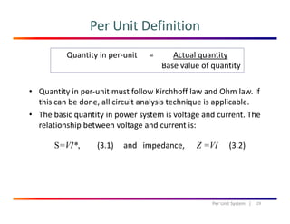
![Three Phase e.m.f/current
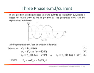
The generated e.m.f is a balance AC voltage because has the same magnitude
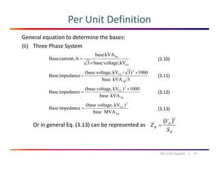
and different phase of 120o. e.m.f also can be represented in a vector form as
shown in Fig. 2.5. E is the magnitude of the e.m.f:
Figure 2.5
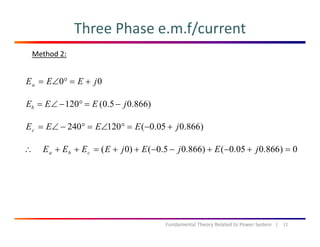
For a balance three phase e.m.f, it can be shown that the sum of these three
e.m.f is equal to zero:
M th d 1Method 1:
0]60cossin2[sin
]60cos)180(sin2[sin
=°=
°°−+=++
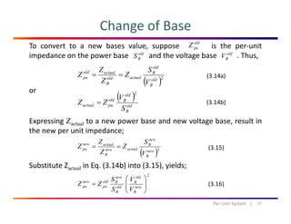
ttE
ttEeee mcba
ωω
ωω
11Fundamental Theory Related to Power System |
0]60cossin2[sin =−= ttEm ωω](https://image.slidesharecdn.com/week2-revision-160318145223/85/Fundamental-Power-System-11-320.jpg)
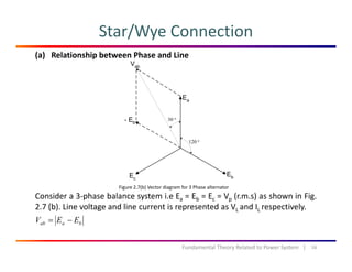
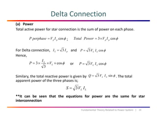
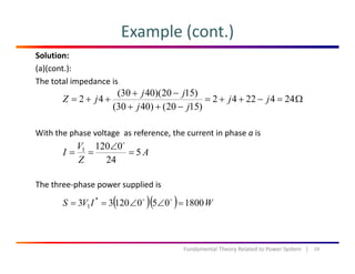
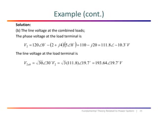
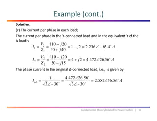

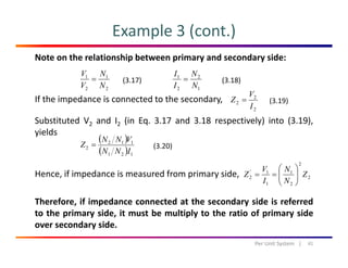

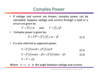
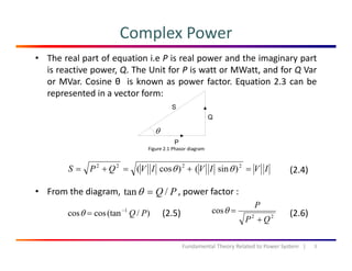
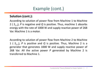
The document discusses fundamental theories related to power systems, including the calculation of complex power, real and reactive power, and the principles of three-phase systems. It features examples illustrating power generation and absorption in interconnected machines and emphasizes the advantages of three-phase systems over single-phase systems. The document also explains different connections, such as star and delta, and their impact on power distribution.


![protection of transmission lines[distance relay protection scheme]](https://cdn.slidesharecdn.com/ss_thumbnails/os-exe3-23-may2011-sr-i-776s21tr-lineprotection-120425095503-phpapp02-thumbnail.jpg?width=640&height=640&fit=bounds)