Downloaded 1,250 times

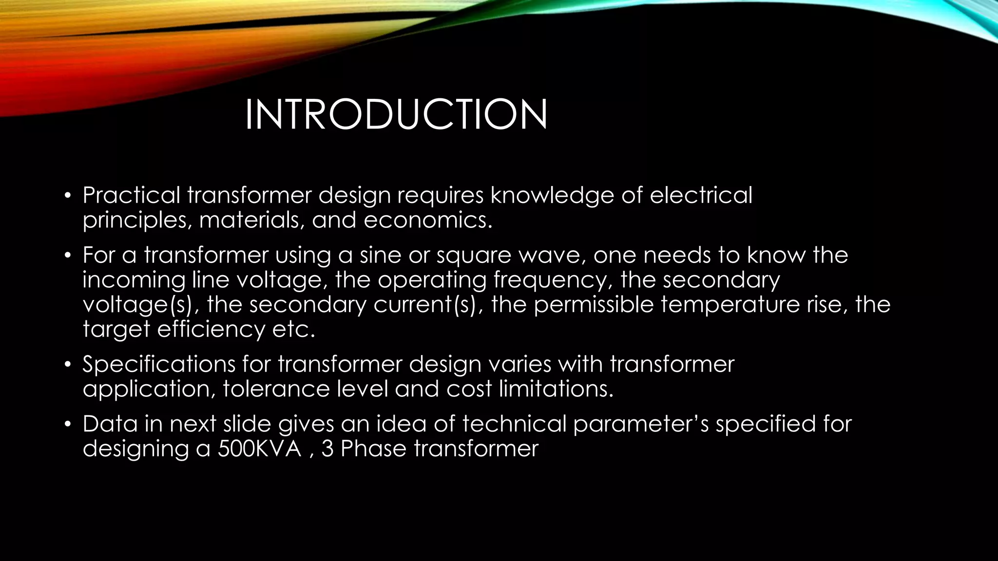
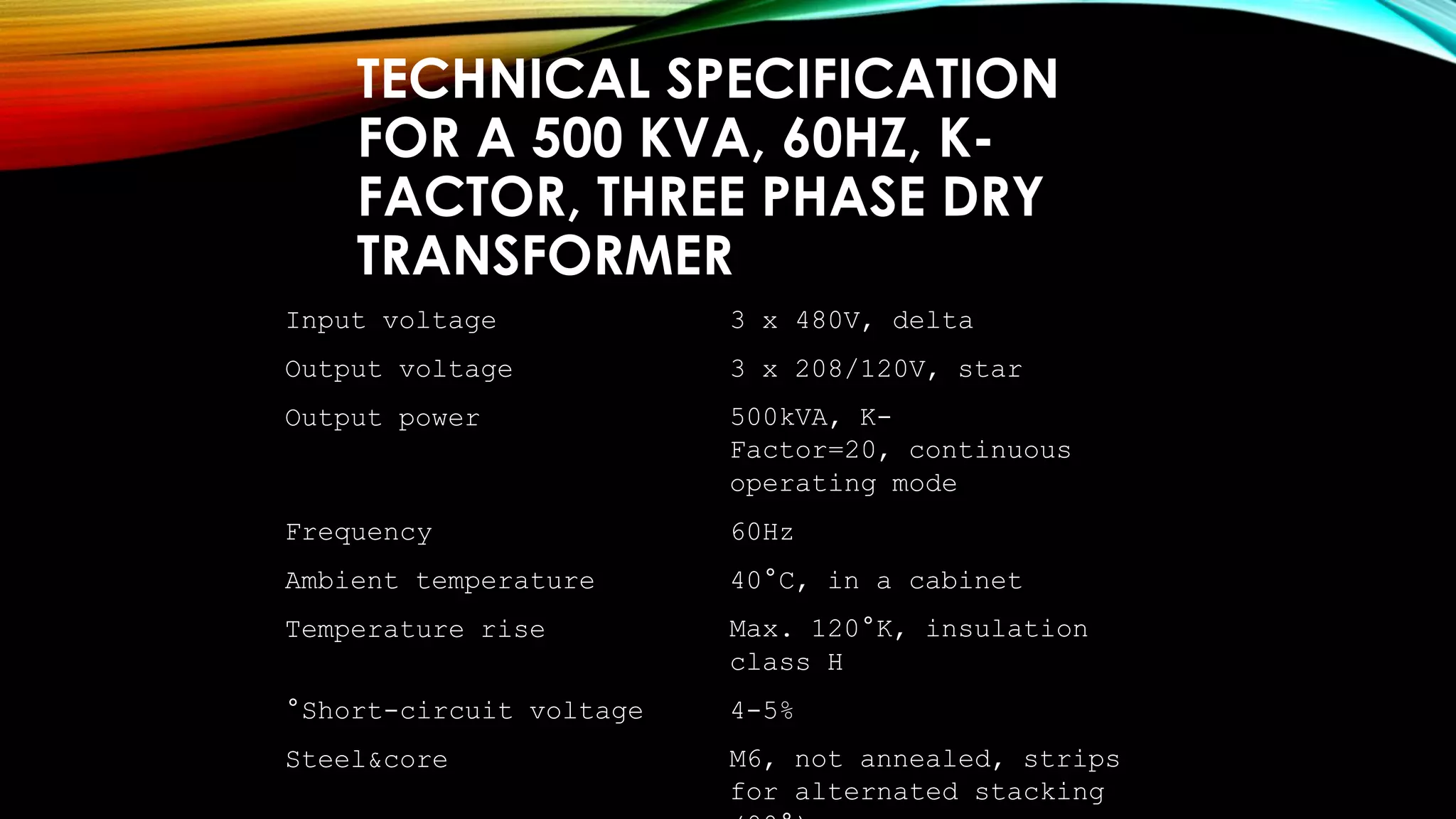

The document provides information on transformer design specifications and considerations. It discusses technical specifications for a 500KVA, 3 phase transformer including input/output voltages and power ratings. It also covers initial calculations, losses in transformers, core materials and construction, winding design, insulation, cooling methods, and connection configurations. The goal is to design a transformer that efficiently transfers power while meeting specifications for voltage, current, temperature rise and other factors.


![Transformer Repair Workshop Report [EEE]](https://cdn.slidesharecdn.com/ss_thumbnails/transformerrepairworkshopeee-140621072318-phpapp01-thumbnail.jpg?width=640&height=640&fit=bounds)